Do you have a question about the Toshiba RAS-12UKPX4 and is the answer not in the manual?
Details on dimensions, net weight, evaporator type, fan, air filter.
Details on dimensions, net weight, condenser type, fan, compressor, safety device, etc.
Details on refrigerant type, rated amount, piping connections.
Details on power source, consumption, operational temperature ranges.
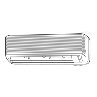
Dimensional drawings and layout of the indoor unit components.
Dimensional drawings and layout for various outdoor units.
Electrical wiring diagram for specific models.
Electrical wiring diagram for specific models.
List and specifications of electrical parts for indoor units.
List and specifications of electrical parts for outdoor units.
Refrigeration cycle diagram for specific models.
Refrigeration cycle diagram for specific models.
Control block diagram for specific heat pump models.
Control block diagram for multiple air conditioner models.
Overview of the air conditioner's control system and sensors.
Explains the sequence of operations for different modes.
Explains the Hi Power mode and its operation.
Describes control to prevent excessive refrigerating cycle pressure.
Describes control to prevent indoor heat exchanger freezing.
Explains defrost operation for heat pump models.
Explains the automatic restart feature after power loss.
Crucial safety precautions before and during installation.
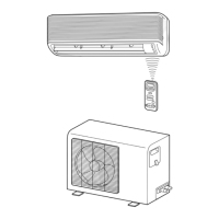
Visual guide for installing indoor and outdoor units.
Procedures for installing the indoor unit.
Procedures for installing the outdoor unit.
Procedure for evacuating air from refrigerant lines.
Procedure for setting remote control selector switch for multiple units.
Instructions for performing a gas leak test.
General steps to follow for troubleshooting.
Initial checks for common issues before detailed troubleshooting.
Using the remote control for self-diagnosis and check codes.
Flowcharts for diagnosing operational issues.
Troubleshooting steps for complete power failure.
Troubleshooting steps when the outdoor unit fails to operate.
Troubleshooting steps when the compressor fails to operate.
Steps to troubleshoot remote control and indoor PC board issues.
Procedures for disassembling and replacing indoor unit parts.
Procedures for disassembling and replacing outdoor unit parts.
Exploded view and parts list for indoor unit (Heat pump model).
Exploded view and parts list for indoor unit (Cooling model).
Exploded view and parts list for specific indoor units.
Exploded view and parts list for a specific outdoor unit.
| Cooling Capacity | 3.5 kW |
|---|---|
| Heating Capacity | 4.0 kW |
| Power Supply | 220-240V, 50Hz |
| Indoor Unit Weight | 9 kg |
| Energy Efficiency Ratio (EER) | 3.21 |
| Coefficient of Performance (COP) | 3.61 |
| Outdoor Unit Noise Level | 49 dB |
| Outdoor Unit Dimensions (WxHxD) | 780 x 550 x 290 mm |