Do you have a question about the Toshiba RAS-13UKHP-E4 and is the answer not in the manual?
| Cooling Capacity | 3.5 kW |
|---|---|
| Heating Capacity | 4.0 kW |
| Energy Efficiency Class (Cooling) | A++ |
| Energy Efficiency Class (Heating) | A+ |
| SEER | 6.1 |
| SCOP | 4.0 |
| Power Supply | 220-240V, 50Hz |
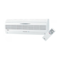
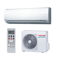
| Type | Air Conditioner |
| Outdoor Unit Noise Level | 50 dB |
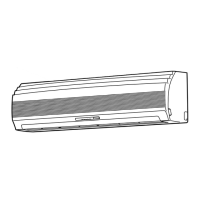
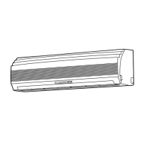
Exploded view and dimensions of the indoor unit components.
Exploded view and dimensions for multiple outdoor unit models.
Exploded view and dimensions for specific outdoor unit models.
Wiring diagram for specific Toshiba air conditioner indoor and outdoor units.
Wiring diagram for specific Toshiba air conditioner indoor and outdoor units.
Wiring diagram for specific Toshiba air conditioner indoor and outdoor units.
Wiring diagram for specific Toshiba air conditioner indoor and outdoor units.
Wiring diagram for specific Toshiba air conditioner indoor and outdoor units.
Wiring diagram for specific Toshiba air conditioner indoor and outdoor units.
Wiring diagram for specific Toshiba air conditioner indoor and outdoor units.
Wiring diagram for specific Toshiba air conditioner indoor and outdoor units.
Electrical specifications for specific indoor unit models.
Electrical specifications for a specific outdoor unit model.
Electrical specifications for a specific outdoor unit model.
Electrical specifications for a specific outdoor unit model.
Electrical specifications for specific indoor unit models.
Electrical specifications for a specific outdoor unit model.
Electrical specifications for specific outdoor unit models.
Electrical specifications for specific outdoor unit models.
Electrical specifications for a specific outdoor unit model.
Electrical specifications for a specific outdoor unit model.
Refrigeration cycle diagram for specific models.
Refrigeration cycle diagram for specific models.
Refrigeration cycle diagram for specific models.
Refrigeration cycle diagram for specific models.
Refrigeration cycle diagram for specific models.
Refrigeration cycle diagram for specific models.
Control block diagram for specific indoor and outdoor unit series.
Control block diagram for multiple indoor and outdoor unit series.
Overview of the air conditioner's control system and components.
Detailed explanation of the air conditioner's operation circuit and logic.
Description of the Hi POWER operating mode for enhanced performance.
Control mechanism to prevent excessive indoor heat exchanger temperature.
Control mechanism to prevent indoor heat exchanger from freezing.
Operation sequence for defrosting the outdoor unit during heating.
Control to prevent specified current values by managing outdoor fan.
Functionality enabling automatic restart after power interruption.
Guide to diagnose and resolve common air conditioner issues.
Procedures for replacing various parts of the air conditioner.
Visual breakdown of components and their part numbers.
Critical safety warnings and precautions before installation.
Visual guide for installing indoor and outdoor units, including placement.
General installation steps and considerations for the unit.
List and details of optional parts for unit installation.
Details of included accessories and parts for installation.
Recommended locations for installing the indoor unit.
Instructions for preparing wall openings and mounting plates.
Procedures for connecting the air conditioner to the electrical power supply.
Steps for connecting refrigerant pipes and drain hoses.
Method for securely mounting the indoor unit onto the installation plate.
Instructions for properly routing and installing the drain hose.
Recommended locations for installing the outdoor unit.
Detailed steps for connecting refrigerant pipes and ensuring tight connections.
Process for purging air and moisture from the refrigerant lines.
Procedure for connecting electrical wiring between indoor and outdoor units.
Procedure for checking the system for refrigerant gas leaks.
Steps to perform a test run of the air conditioner.
Instructions for enabling the auto restart function after power failure.
General guide for troubleshooting air conditioner issues.
Initial checks to perform before detailed troubleshooting.
Basic steps for diagnosing unit problems based on symptoms.
Explanation of the indoor unit controller's functions and inputs.
How the unit diagnoses failures and indicates them via lamps.
Procedure for diagnosing faults using remote control check codes.
Guide on accessing and using the remote control's service mode.
Diagnostic flowcharts for various operational issues.
Flowchart for diagnosing issues when the unit does not turn on.
Troubleshooting flowchart after P.C. board replacement.
Flowchart for diagnosing why the outdoor unit is not operating.
Flowchart for diagnosing issues specific to the compressor.
Flowchart for diagnosing issues with the outdoor fan.
Flowchart for diagnosing 4-way valve failure during heating.
Flowchart for diagnosing issues with the indoor fan.
Troubleshooting steps for remote control and indoor P.C. board issues.
Procedure for inspecting and checking the Printed Circuit Board.
Procedures for disassembling and replacing indoor unit components.
Procedures for disassembling and replacing outdoor unit components.
Exploded view and parts list for the indoor unit heat pump model.
Exploded view and parts list for the indoor unit cooling model.
Exploded view and parts list for specific indoor unit models.
Exploded view and parts list for specific indoor unit models.
Exploded view and parts list for a specific outdoor unit model.
Exploded view and parts list for a specific outdoor unit model.
Exploded view and parts list for a specific outdoor unit model.
Exploded view and parts list for a specific outdoor unit model.
Exploded view and parts list for specific outdoor unit models.
Exploded view and parts list for a specific outdoor unit model.
Exploded view and parts list for specific outdoor unit models.
Exploded view and parts list for a specific outdoor unit model.