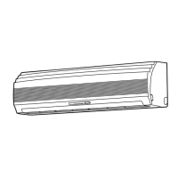
Do you have a question about the Toshiba RAS-13UKPX2 and is the answer not in the manual?
| Cooling Capacity | 3.5 kW |
|---|---|
| Heating Capacity | 4.0 kW |
| Refrigerant | R32 |
| Power Supply | 220-240V, 50Hz |
| Noise Level (Outdoor) | 50 dB(A) |
| Outdoor Unit Dimensions (WxHxD) | 780 x 550 x 285 mm |
Step-by-step guide for diagnosing issues and performing essential initial checks.
Initial diagnosis based on symptoms and common failures.
Using the remote control for fault code retrieval and diagnosis.
Visual guides to systematically diagnose operational problems.
Steps for troubleshooting the remote control and P.C. board.
Guidelines for safe installation of the air conditioner.
Visual guide for unit placement and connections.
Steps for installing the indoor unit: place, fix, electrical, piping.
Steps for installing the outdoor unit: drainage and location selection.
How to set the remote control selector switch for multiple units.
Procedures for replacing internal components of the indoor unit.
Procedures for replacing internal components of the outdoor unit.
Diagrams showing indoor unit components and their part numbers.
Diagrams showing outdoor unit components and their part numbers.
Detailed technical specifications for various air conditioner models.
Dimensions, air volume, and filter details for indoor units.
Dimensions, fan types, and compressor details for outdoor units.
Detailed diagrams of the indoor unit's physical structure and dimensions.
Detailed diagrams of the outdoor unit's physical structure and dimensions.
Electrical schematic showing connections for specific indoor/outdoor models.
Electrical schematic showing connections for specific indoor/outdoor models.
Electrical schematic covering several indoor/outdoor unit combinations.
Detailed list of electrical components for specific indoor unit models.
Detailed list of electrical components for the RAS-13UAH-E2 outdoor unit.
Detailed list of electrical components for the RAS-10UAH-E2 outdoor unit.
Detailed list of electrical components for various indoor unit models.
Detailed list of electrical components for the RAS-13UA-E2 outdoor unit.
Detailed list of electrical components for the RAS-13UAX2 outdoor unit.
Detailed list of electrical components for the RAS-10UA-E2 outdoor unit.
Schematic of the refrigeration system and operating parameters.
Schematic of the refrigeration system and operating parameters.
Schematic of the refrigeration system and operating parameters.
Schematic of the refrigeration system and operating parameters.
Schematic of the refrigeration system and operating parameters.
Schematic of the refrigeration system and operating parameters.
System control logic for specified indoor/outdoor unit models.
System control logic for specified indoor/outdoor unit models.
General overview of the air conditioner's control system and functions.
Description of indoor unit louver and fan motor operation modes.
Detailed descriptions of various operating modes and their control logic.
Hi POWER, temperature limits, defrost, and current limit controls.
Procedures for auto restart function and filter check lamp management.
Lists of optional parts and standard accessories for installation.
Guidelines for selecting a suitable location for indoor unit installation.
Procedures for making electrical connections and wiring requirements.
Steps for connecting the power cord and connecting cables to the unit.
Instructions for routing and connecting refrigerant pipes and drain hoses.
Methods for securely mounting the indoor unit onto the installation plate.
Procedures for testing for gas leaks and performing a unit test operation.
Flowchart to diagnose issues when the unit does not turn on.
Troubleshooting steps after replacing the indoor unit's P.C. board.
Flowchart to diagnose why the outdoor unit is not operating.
Diagnosing issues when only the compressor fails to operate.
Diagnosing issues when only the outdoor fan fails to operate.
Diagnosing issues with the 4-way valve during heating operation.
Diagnosing issues when only the indoor fan fails to operate.
Comprehensive guide to troubleshoot remote control and indoor P.C. board issues.
Diagrams showing indoor unit components and their part numbers.
Diagrams showing outdoor unit components and their part numbers.


