Do you have a question about the Toshiba RAS-13YA-E and is the answer not in the manual?
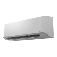
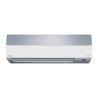
Diagrams and dimensions of the indoor unit.
Diagrams and dimensions of the outdoor unit.
List of electrical parts and their specifications for the indoor unit.
List of electrical parts and their specifications for the outdoor unit.
Describes the FAN ONLY operating mode and fan speed settings.
Explains compressor, 4-way valve, and outdoor fan control during COOL operation.
Details the compressor, 4-way valve, and fan operation during DRY mode.
Explains operation and fan control for the HEAT mode.
Describes automatic mode selection based on room temperature.
Explains the ECONO. mode for quiet and mild operation.
Microprocessor control to prevent exceeding specified input current.
Prevents condensate pressure from exceeding limits during heating.
Prevents freezing of the indoor heat exchanger during cooling.
Operation when outdoor heat exchanger freezes during heating.
Facility for automatic unit restart after power failure.
Crucial safety precautions for installation work.
Diagrams illustrating indoor and outdoor unit installation.
Guidelines for selecting the indoor unit installation place.
Details on electrical requirements and connections for the air conditioner.
Detailed instructions for connecting refrigerant piping with flaring and tightening.
Procedure for vacuum pumping the refrigerant system.
Guidelines for selecting the outdoor unit installation place.
How to perform a gas leak test after installation.
Procedure for switching to and performing a test run.
Initial checks to perform before detailed troubleshooting.
Initial diagnosis of potential problems based on symptoms and block displays.
How to use the remote control for self-diagnosis and check codes.
Step-by-step flowcharts for diagnosing various operational issues.
Procedures for replacing parts of the indoor unit.
Procedures related to microcomputer and thermal fuse replacement.
Procedures for replacing parts of the outdoor unit.
Exploded view and parts list for the indoor unit (part 1).
Exploded view and parts list for the indoor unit (part 2).
Exploded view and parts list for the outdoor unit.
| Type | Split System |
|---|---|
| Cooling Capacity | 3.5 kW |
| Heating Capacity | 4.0 kW |
| Refrigerant | R410A |
| Power Supply | 220-240V, 50Hz |
| Indoor Unit Weight | 9 kg |
| Noise Level (Outdoor) | 50 dB |