Do you have a question about the Toshiba RAS-167SKV-E3 and is the answer not in the manual?
Detailed technical specifications for cooling, heating, power, and dimensions.
Safety measures for installation and servicing with R410A refrigerant.
Guidelines for refrigerant piping installation, materials, and joints.
Lists tools exclusive for R410A and general tools.
Step-by-step procedure for recharging refrigerant.
Materials and methods for brazing refrigerant pipes.
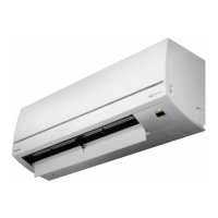
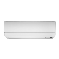
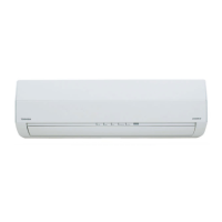
Diagrams and dimensions of the indoor unit.
Diagrams and dimensions of the outdoor unit.
Wiring diagram for specific indoor/outdoor unit models.
Wiring diagram for specific indoor/outdoor unit models.
List of electrical components for indoor units.
List of electrical components for outdoor units.
Diagram showing the refrigerant flow and key components.
Operational data under various cooling and heating conditions.
Block diagram illustrating the indoor unit's control functions.
Block diagram illustrating the outdoor unit's control logic.
Overview of the air conditioner's control system and functions.
Details on basic cooling, heating, auto, dry, and fan control operations.
Explains ECO, QUIET, COMFORT SLEEP, and Hi-POWER modes.
Covers auto restart setup and remote controller functions.
Covers placement, drilling, mounting plate, electrical work, and piping for the indoor unit.
Covers placement, draining, piping, evacuation, and wiring for the outdoor unit.
Includes gas leak test, system test, auto restart, and remote control settings.
Performing initial checks and primary judgments for troubleshooting.
Using LED indicators and remote controller for self-diagnosis and error code interpretation.
Diagnosing issues based on specific symptoms like no power or fan motor problems.
Step-by-step checks for main parts like P.C. boards, sensors, and motors.
Step-by-step guide for replacing main components of the indoor unit.
Step-by-step guide for replacing main components of the outdoor unit.
Exploded views and parts lists for indoor units.
Exploded views and parts lists for outdoor units.
Layout diagrams for PC boards of various models.
| Brand | Toshiba |
|---|---|
| Model | RAS-167SKV-E3 |
| Category | Air Conditioner |
| Language | English |