Do you have a question about the Toshiba RAS-167SKV-E5 and is the answer not in the manual?
Precautions for safe installation and servicing with R410A refrigerant.
Guidelines for installing refrigerant piping, including materials and joints.
Lists tools exclusive to R410A and general tools for installation.
Explains types of silver and phosphor bronze brazing fillers.
Details on preventing oxidation during brazing.
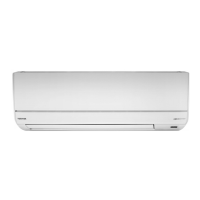
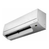
Diagrams and dimensions of the indoor unit and its parts.
Lists electrical parts used in the indoor unit with their specifications.
Lists electrical parts used in the outdoor unit with their specifications.
Block diagram showing the control functions of the indoor unit.
Overview of the air conditioner's capacity-variable control system.
Explains basic operations, fan control, and mode selections.
Details on setting and canceling the auto restart function.
Explains the functions and operations of the remote controller.
Illustrates placement and clearances for indoor and outdoor units.
Guidelines for selecting an appropriate location for the indoor unit.
Instructions for cutting wall holes and mounting the installation plate.
Procedures for checking refrigerant gas connections for leaks.
How to perform a test run of the air conditioner.
Verifies power supply, voltage, and normal operation status.
Initial diagnosis methods including LED flashing and remote controller self-diagnosis.
Interprets indoor unit LED flashing codes for self-diagnosis.
Using the remote controller in service mode to diagnose faults via check codes.
Diagnosing issues based on observed symptoms like no power or fan malfunction.
Troubleshooting guide for miswiring and discharge temperature errors.
Procedures for diagnosing inverter assembly issues in the outdoor unit.
Steps for checking the indoor unit's P.C. board and its components.
Method to determine the condition of the outdoor fan motor.
Procedures for replacing main parts of the indoor unit.
Exploded view and parts list for the indoor unit's electronic components.
Exploded view and parts list for the indoor unit's mechanical components.
Exploded view and parts list for the outdoor unit's components.
Diagram showing the layout of components on the P.C. board.
| Type | Split System |
|---|---|
| Heating Capacity | 5.0 kW |
| Power Supply | 220-240 V, 50 Hz |
| Refrigerant | R410A |
| Energy Efficiency Ratio (EER) | 3.21 |
| Coefficient of Performance (COP) | 3.61 |
| Outdoor Unit Dimensions (WxHxD) | 780x550x290 mm |
| Noise Level (Outdoor Unit) | 52 dB(A) |