4
INDOOR UNIT
Installation Place
• Direct sunlight to the indoor unit’s wireless receiver should be avoided.
• The microprocessor in the indoor unit should not be too close to RF
noise sources.
(For details, see the owner’s manual.)
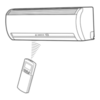
Remote control
• A place where there are no obstacles such as a curtain that may block the
signal from the remote control.
• Do not install the remote control in a place exposed to direct sunlight or
close to a heating source such as a stove.
• Keep the remote control at least 1 m apart from the nearest TV set or stereo
equipment. (This is necessary to prevent image disturbances or noise
interference.)
• The location of the remote control should be determined as shown below.
Cutting a Hole and Mounting
Installation Plate
NOTE
• When drilling a wall that contains a metal lath, wire lath or metal plate, be
sure to use a pipe hole brim ring sold separately.
Cutting a hole
When installing the refrigerant pipes from the rear
Mounting the installation plate
When the installation plate is directly mounted
on the wall
1. Securely fi t the installation plate onto the wall by screwing it in the upper
and lower parts to hook up the indoor unit.
2. To mount the installation plate on a concrete wall with anchor bolts, use the
anchor bolt holes as illustrated in the below fi gure.
3. Install the installation plate horizontally in the wall.
When installing the installation plate with a mounting screw, do not use
the anchor bolt holes. Otherwise, the unit may fall down and result in
personal injury and property damage.
1. After determining the pipe hole position on the mounting plate (➡), drill the
pipe hole (dia. 65 mm) at a slight downward slant to the outdoor side.
• A place which provides the spaces around the indoor unit as shown in the
diagram
• A place where there are no obstacles near the air inlet and outlet
• A place which allows easy installation of the piping to the outdoor unit
• A place which allows the front panel to be opened
• The indoor unit shall be installed as top of the indoor unit comes to at least
2 m height. Also, it must be avoided to put anything on the top of the indoor
unit.
CAUTION
m from the right side edge is
center of pipe hole
35 120 180 240
The center of the pipe hole is above
the arrow.
Pipe hole
CAUTION
Failure to fi rmly install the unit may result in personal injury and property
damage if the unit falls.
• In case of block, brick, concrete or similar type walls, make 5 mm dia. holes
in the wall.
• Insert clip anchors for appropriate mounting screws 7.
NOTE
• Secure four corners and lower parts of the installation plate with 4 to 6
mounting screws to install it.
CAUTION
23mm
dia. 65mm
7
Installation plate
(Keep horizontal direction.)
5 mm dia. hole
Mounting screw
dia. 4 mm x 25R
Clip anchor
(local parts)
Anchor bolt
Projection
15 mm or less
7RXQLWRXWOLQH
PP
7RXQLWRXWOLQH
PP
7RXQLWRXWOLQH
PP
2IIVHWPPIURPWKHULJKWVLGHHGJHLV
WKHFHQWHURISLSHKROH
7RXQLWRXWOLQH
PP
2IIVHWPPIURPWKHOHIWVLGHHGJHLV
WKHFHQWHURISLSHKROH
1
7
Anchor bolt holes
Hook
Hook
Hook
Pipe hole
Pipe hole
(dia. 65mm)
Installation plate
Weight
Indoor unit
Thread
2 m or more from fl oor
Mounting
Screw
dia. 65mm
54 °
4
5°
5
7
°
(Side view) (Top view)
Indoor unit
Reception range
Remote
control
Remote
control
Reception
range
Indoor unit
Wiring Connection
Wiring of the connecting cable can be carried out without removing the
front panel.
1. Remove the air inlet grille.
Open the air inlet grille upward and pull it toward you.
2. Remove the terminal cover and cord clamp.
3. Insert the connecting cable (according to the local rule) into the pipe hole
on the wall.
4. Take out the connecting cable through the cable slot on the rear panel so
that it protrudes about 15 cm from the front.
5. Insert the connecting cable fully into the terminal block and secure it tightly
with screws.
6. Tighten fi rmly but not over 1.2 N·m (0.12 kgf·m)
7. Secure the connecting cable with the cord clamp.
8. Fix the terminal cover, rear plate bushing and air inlet grille on the indoor
unit.
How to connect the connecting cable

 Loading...