Do you have a question about the Toshiba RAS-18SKP-E and is the answer not in the manual?
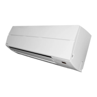
Diagrams and dimensions of the indoor unit.
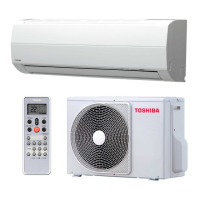
Diagrams and dimensions of the 18 Class outdoor unit.
Diagrams and dimensions of the 24 Class outdoor unit.
Wiring diagram for specific models (18 Class).
Wiring diagram for specific models (24 Class).
Electrical part specifications for indoor units (18 Class).
Electrical part specifications for outdoor units (18 Class).
Electrical part specifications for indoor units (24 Class).
Electrical part specifications for outdoor units (24 Class).
Refrigeration cycle diagram for 18 Class models.
Refrigeration cycle diagram for 24 Class models.
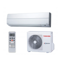
Details function, display, and buttons of the remote control.
Explains roles of indoor/outdoor controllers and system logic.
Describes vertical airflow louver control (position and swing).
Explains indoor fan speed control based on operation modes.
Describes different operation modes like Fan only, Cooling, Dry, Auto.
Details fan-only operation settings and fan speed control.
Explains cooling operation control for compressor, fan, and display.
Details dry operation control for compressor, fan, and display.
Explains automatic operation selection based on temperature.
Explains functions like low-temperature limit control.
Details the fully automated one-touch comfort operation.
Covers Hi POWER, QUIET, and ECO operations.
Details the COMFORT SLEEP mode for enhanced comfort and energy saving.
Explains filter lamp and timer-related operations.
Describes the auto restart function after power failure.
Provides steps to enable the auto restart function.
Explains how to disable the auto restart function.
Notes the effect of power failure on timer operations.
Explains the self-cleaning operation to keep the unit clean.
Illustrates the self-cleaning operation sequence and conditions.
Details how to cancel and set the self-cleaning function.
Crucial safety warnings and precautions for installation.
Visual guide for installing indoor and outdoor units with dimensions.
Covers optional parts and accessories for installation.
Lists and describes optional parts for installation.
Lists accessories and installation parts with their illustrations.
Details regarding indoor unit installation.
Specifies ideal locations and conditions for indoor unit installation.
Instructions for drilling wall holes and mounting the installation plate.
Details electrical wiring requirements and connection methods.
Steps for connecting the connecting cable to the indoor unit.
Guides on forming pipes, drain hoses, and installation.
Steps for physically mounting the indoor unit onto the installation plate.
Instructions for ensuring proper drainage from the indoor unit.
Details regarding outdoor unit installation.
Specifies ideal locations and conditions for outdoor unit installation.
Details how to connect refrigerant pipes, including flaring.
Instructions for evacuating air from the refrigerant system using a vacuum pump.
Steps for connecting power supply and connecting cables to the outdoor unit.
Covers gas leak test, test operation, and settings.
Procedures for checking refrigerant gas leaks after installation.
Steps to perform a test run of the air conditioner system.
Instructions for setting the auto restart function.
Explains how to set remote control A/B selection for multiple units.
General steps for troubleshooting the air conditioner.
Lists basic checks for power, connections, and voltage.
Checks if the power supply voltage is within the specified range.
Verifies correct cable connections between indoor and outdoor units.
Explains microcontroller operation and checking against problems.
Provides initial diagnosis based on symptoms and lamp indicators.
Describes the functions of the indoor unit controller.
Explains how the unit self-diagnoses and indicates faults.
Guides for self-diagnosis and reading check codes via remote controller.
Provides steps to enter service mode and navigate check codes.
Guides for diagnosing and resolving indoor unit issues.
Troubleshooting steps when the unit does not turn on.
Troubleshooting steps when only the indoor fan motor fails to operate.
Troubleshooting steps when the compressor does not operate.
Guides for diagnosing wiring issues between units.
Checks voltage and signal transmission for outdoor unit operation.
Diagnoses issues causing the outdoor unit to stop and restart.
Guides for diagnosing and resolving issues related to the P.C. board.
Procedures for inspecting the indoor unit's P.C. board for defects.
Guides for diagnosing and resolving issues with the remote control.
Procedures for replacing main parts of the indoor unit.
Procedures for replacing main parts of the 18 Class outdoor unit.
Procedures for replacing main parts of the 24 Class outdoor unit.
Exploded view and parts list for the indoor unit (E-Parts Assy).
Exploded view and parts list for the indoor unit.
Exploded view and parts list for the 18 Class outdoor unit.
Exploded view and parts list for the 24 Class outdoor unit.
| Type | Split System |
|---|---|
| Cooling Capacity | 5.0 kW |
| Power Supply | 220-240V, 50Hz |
| Refrigerant | R410A |
| Coefficient of Performance (COP) | 3.61 |
| Outdoor Unit Dimensions (HxWxD) | 550x780x290 mm |
| Noise Level (Outdoor) | 50 dB |