Do you have a question about the Toshiba RAS-18UFHP-E3 and is the answer not in the manual?
| Brand | Toshiba |
|---|---|
| Model | RAS-18UFHP-E3 |
| Category | Air Conditioner |
| Language | English |
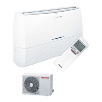
Detailed diagrams and dimensions of the indoor unit for installation and component identification.
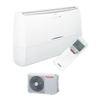
Diagrams and dimensions for the RAS-18UAH-E3 outdoor unit, showing installation details.
Visual representation and dimensions for RAS-18UA-E3, RAS-18UAX3, and RAS-18UA-AR3 outdoor units.
Construction views and dimensions for various RAS-24UA and related outdoor units.
Electrical schematic detailing connections for RAS-18UFHP-E3 and RAS-18UAH-E3 models.
Wiring diagram for RAS-18UFP-E3, RAS-18UA-E3, RAS-18UFPX3, and RAS-18UAX3 models.
Wiring schematic for RAS-18UFP-AR3 and RAS-18UA-AR3 models.
Wiring diagram for RAS-18UFPX3-T2 and RAS-18UAX3-T2 models.
Electrical schematic for RAS-24UFHP-E3 and RAS-24UAH-E3 models.
Wiring diagrams for various RAS-24UFP/UA models, including different series.
List and specifications of electrical components used in the indoor unit.
Detailed specifications for electrical parts of the RAS-18UAH-E3 outdoor unit.
Electrical component specifications for RAS-18UAX3 and RAS-18UA-E3 outdoor units.
Specifications of electrical parts for the RAS-18UA-AR3 outdoor unit.
Electrical parts specifications for the RAS-18UAX3-T2 outdoor unit.
Critical safety precautions to be followed before and during installation.
Visual guide showing placement and connections for indoor and outdoor units.
Detailed steps for connecting the refrigerant pipes, including flaring.
Instructions for connecting electrical wiring to the outdoor unit.
Procedures for evacuating the refrigerant system using a vacuum pump.
General steps for diagnosing and resolving issues with the air conditioner.
Using the remote control to access and interpret self-diagnosis error codes.
Diagnostic flowcharts to identify specific faulty parts based on symptoms.
Specific troubleshooting steps for issues related to the indoor unit.
Procedures for troubleshooting and inspecting the Printed Circuit Board.
Guide for inspecting the outdoor P.C. board for faults and damage.
Initial checks to perform before detailed troubleshooting.
Step-by-step guide to enter and use the remote control's service mode for diagnosis.
Procedure for when the indoor unit fails to power on or operate.
Troubleshooting steps for when the compressor fails to operate.
Guide for inspecting the indoor P.C. board for faults and damage.