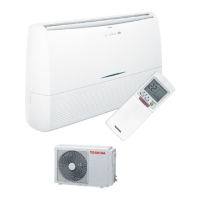
Do you have a question about the Toshiba RAS-18UKPX3 and is the answer not in the manual?
Technical specifications for 24 series outdoor and indoor units.
Technical specifications for 18 series outdoor and indoor units.
Details on refrigerant type, capacity conditions, and charging.
Detailed dimensions and installation points for the indoor unit.
Dimensions for specific 24 and 18 series outdoor units.
Installation dimensions for the RAS-18UAH-E3 outdoor unit.
Installation dimensions for RAS-18UA-E3, RAS-18UAX3, RAS-18UA-AR3 models.
Wiring schematic for specific 24 series indoor and outdoor units.
Wiring schematic for specific 18 series indoor and outdoor units.
Wiring schematics for various 24 series models.
Wiring schematics for various 18 series models.
Wiring schematic for specific 18 series models.
Wiring schematic for specific 18 series models.
Electrical component specifications for specific indoor units.
Electrical component specifications for the RAS-24UAH-E3 outdoor unit.
Electrical component specifications for the RAS-18UAH-E3 outdoor unit.
Electrical component specifications for specific indoor units.
Electrical component specifications for specific 24UA series outdoor units.
Electrical component specifications for specific 18UA series outdoor units.
Diagram and operating conditions for specific 24 series models.
Diagram and operating conditions for specific 18 series models.
Diagram and operating conditions for specific 24 series models.
Diagram and operating conditions for specific 24 series models.
Diagram and operating conditions for specific 18 series models.
Diagram and operating conditions for specific 18 series models.
Diagram and operating conditions for specific 18 series models.
Diagram and operating conditions for specific 18 series models.
Control logic block diagram for specific indoor and outdoor units.
Control logic block diagram for various 18 and 24 series models.
Overview of indoor and outdoor unit control functions.
Description of vertical air flow louver and indoor DC fan motor control.
Description of operation circuit for fan, cooling, and dry modes.
Description of operation circuit for heating mode.
Explanation of automatic and temporary auto operation modes.
Details on Hi POWER mode, limit controls, and defrost operation.
Setup and cancellation of auto restart and filter check functions.
Description, cancellation, and setting of the self-cleaning function.
Critical safety warnings and precautions before installation.
Requirements for reporting installation to the local power supplier.
Visual guide for installing indoor and outdoor units.
Lists optional parts and accessories for installation.
Guidelines for selecting the indoor unit location and cutting wall holes.
Instructions for electrical wiring and securely mounting the indoor unit.
Step-by-step guide for connecting indoor unit wiring.
Procedures for connecting refrigerant pipes and drain hoses.
Steps for securing the indoor unit and ensuring proper drainage.
Guidelines for outdoor unit location and refrigerant piping.
Steps for evacuating refrigerant pipes using a vacuum pump.
Connecting outdoor unit wiring and charging refrigerant.
How to set the remote control selector switch for multi-unit systems.
Procedures for gas leak testing, test operation, and auto restart setup.
Initial checks for power, connections, and program control.
Basic troubleshooting steps and lamp-based self-diagnosis.
Using the remote control for detailed error code diagnosis.
Diagnosis flowcharts for indoor and outdoor sensor errors.
Troubleshooting steps for power issues and indoor fan motor failures.
Troubleshooting for compressor operation and heating mode issues.
Troubleshooting for wiring issues and outdoor unit stopping.
Procedures for checking the P.C. board and timer functions.
Step-by-step guide to diagnose and fix remote control issues.
Steps for replacing front panel and electrical parts in the indoor unit.
Procedures for replacing components in 24 series outdoor units.
Procedures for replacing components in the RAS-18UAH-E3 outdoor unit.
Procedures for replacing components in 18UA series outdoor units.
Procedures for replacing components in the RAS-18UAX3-T2 outdoor unit.
Exploded view and parts list for the indoor unit's electrical assembly.
Exploded view and parts list for the indoor unit components.
Exploded view and parts list for the RAS-24UAH-E3 outdoor unit.
Exploded view and parts list for the RAS-18UAH-E3 outdoor unit.
Exploded view and parts list for the RAS-24UA series outdoor units.
Exploded view and parts list for the RAS-24UA-AR3 outdoor unit.
Exploded view and parts list for the RAS-18UAX3-T2 outdoor unit.
Exploded view and parts list for the RAS-18UA series outdoor units.
Exploded view and parts list for the RAS-18UA-AR3 outdoor unit.
| Cooling Capacity | 5.0 kW |
|---|---|
| EER | 3.21 |
| Refrigerant | R32 |
| Power Supply | 220-240V, 50Hz |
| Noise Level (Outdoor Unit) | 52 dB(A) |
| Outdoor Unit Weight | 30 kg |
| Type | Split System |


 Loading...