EasyManua.ls Logo

Toshiba RAS-24N3AV2-A User Manual

Toshiba RAS-24N3AV2-A
129 pages
To Next Page IconTo Next Page
Page #1 background imageLoading...
Page #1 background image
R410A
AIR-CONDITIONER
SPLIT TYPE
SERVICE MANUAL
Indoor Unit Outdoor Unit
<High Wall, Heat Pump Type> <Heat Pump Type>
FILE NO. SVM-13004
RAS-24N3KV2-A RAS-24N3AV2-A
February,2013

Table of Contents

Question and Answer IconNeed help?

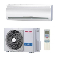
Do you have a question about the Toshiba RAS-24N3AV2-A and is the answer not in the manual?

Toshiba RAS-24N3AV2-A Specifications

General IconGeneral
BrandToshiba
ModelRAS-24N3AV2-A
CategoryAir Conditioner
LanguageEnglish

Summary

Precautions for Safety

New Refrigerant Air Conditioner Installation

Precautions for installing the new HFC refrigerant (R410A) air conditioner, emphasizing safety.

Specifications

Specifications

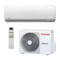
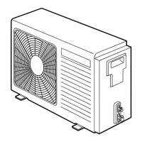
Detailed technical specifications for both indoor and outdoor units, including capacities, power, dimensions, and accessories.

Refrigerant R410A

Safety During Installation/Servicing

Safety precautions and procedures for handling R410A refrigerant during installation and servicing.

Refrigerant Piping Installation

Information on suitable copper pipes, joints, and their specifications for R410A refrigerant.

Processing of Piping Materials

Procedures and precautions for processing piping materials, including cutting, burrs, and flare nut insertion.

Tools

Required Tools

Lists tools required for R410A installation, distinguishing between exclusive and general tools.

Recharging of Refrigerant

Brazing of Pipes

Materials for Brazing

Details on silver brazing filler, phosphor bronze filler, and low-temperature brazing filler for pipe joining.

Flux

Explanation of why flux is necessary and its role in brazing.

Brazing

Wiring Diagram

Specifications of Electrical Parts

Refrigerant Cycle Diagram

Control Block Diagram

Operation Description

Indoor Fan Motor Control

Outdoor Fan Control

Capacity Control

Current Release Control

High-Pressure Release Control

Release Protective Control by Temperature of Indoor Heat Exchanger

Defrost Control (Only in Heating Operation)

Discharge Temperature Control

Pulse Modulating Valve (PMV) Control

Auto Restart Function

Installation Procedure

Installation Diagram of Indoor and Outdoor Units

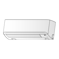
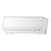
Illustrates the physical placement and installation layout of indoor and outdoor units.

Indoor Unit

Wiring Connection

Piping and Drain Hose Installation

Indoor Unit Fixing

Drainage

Installation Place

Refrigerant Piping

Refrigerant Piping Connection

Detailed instructions for connecting the refrigerant piping, including flaring and dimensions.

Evacuating

Electrical Work

Earthing

Test Run

Troubleshooting

Restrictions for Use of Existing Pipes

How to Diagnose the Trouble

First Confirmation

Initial checks to perform before diagnosing troubles, including power supply and voltage.

Confirmation of Power Supply

Confirmation of Power Voltage

Primary Judgment

Judgment by Flashing LED of Indoor Unit

Self-Diagnosis by Remote Controller (Check Code)

How to Use Remote Controller in Service Mode

Step-by-step instructions for accessing and navigating the remote controller's service mode.

Caution at Servicing

Judgement of Trouble by Every Symptom

Indoor Unit (Including Remote Controller)

Troubleshooting steps for indoor unit issues, including remote controller problems.

Wiring Failure (Interconnecting and Serial Signal Wire)

How to Check Simply the Main Parts

Indoor Unit (Other Parts)

Outdoor Unit

How to Simply Judge Whether Outdoor Fan Motor is Good or Bad

How to Replace the Main Parts

Indoor Unit

Procedure for removing and assembling the front panel of the indoor unit.

Electric Parts Box Assembly

Evaporator (Heat Exchanger)

Fan Motor

Cross Flow Fan

Control P.C. Board

Reactor

Removal of Broken Compressor

Mounting of Compressor

Vacuuming

Refrigerant Charging

PMV Coil

P.C. Board Layout (Outdoor)

Related product manuals