Do you have a question about the Toshiba RAS-24NA-E and is the answer not in the manual?
| Cooling Capacity | 6.5 kW |
|---|---|
| Refrigerant | R410A |
| Weight (Indoor Unit) | 14 kg |
| Weight (Outdoor Unit) | 44 kg |
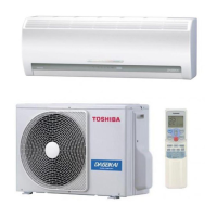
| Type | Split System |
| Power Supply | 220-240 V |
Lists specifications for the 18 Class models.
Lists specifications for the 24 Class models.
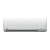
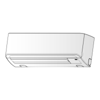
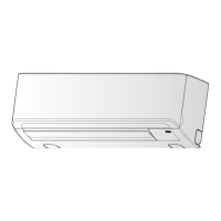
Details the physical construction of the indoor unit.
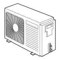
Shows the external construction of the 24 Class outdoor unit.
Shows the external construction of the 18 Class outdoor unit.
Wiring diagram for specific 18 Class models.
Wiring diagram for specific 18 Class models.
Wiring diagram for specific 24 Class models.
Wiring diagram for specific 24 Class models.
Lists electrical components for the Indoor Unit.
Lists electrical components for the 18NAH-E Outdoor Unit.
Lists electrical components for 18NA-E/18N2AX Outdoor Units.
Lists electrical components for the 24NAH-E Outdoor Unit.
Lists electrical components for 24NA-E/24N2AX Outdoor Units.
Refrigeration cycle diagram for specific 18 Class models.
Refrigeration cycle diagram for specific 18 Class models.
Refrigeration cycle diagram for specific 24 Class models.
Refrigeration cycle diagram for specific 24 Class models.
Control block diagram for specific models.
Control block diagram for specific models.
Provides a general overview of the air conditioner control system.
Explains Cooling, Dry, Heating, and Automatic operation modes.
Details Hi Power, Quiet, and Comfort Sleep modes.
Describes how to set and use the auto restart function.
Explains the filter check lamp function and reset procedure.
Details the self-cleaning function for humidity reduction.
Essential safety precautions for installation.
Visual guides for indoor and outdoor unit installation.
Lists necessary parts and accessories for installation.
Covers placement, mounting, wiring, and drainage for indoor units.
Covers placement, piping, evacuation, and wiring for outdoor units.
Explains how to set the remote control selector switch.
Covers gas leak test, test operation, and auto restart.
Covers basic checks, cable issues, program control, and primary judgment.
Guides for performing self-diagnosis using the remote control.
Flowcharts for diagnosing specific faulty parts and errors.
Procedures for troubleshooting indoor unit operational issues.
Steps for troubleshooting issues related to the P.C. board.
Procedures for replacing indoor unit components like grille and panel.
Procedures for replacing parts in 24 Class outdoor units.
Procedures for replacing parts in 18 Class outdoor units.
Exploded view and parts list for the indoor unit's E-Parts Assy.
Exploded view and parts list for the indoor unit components.
Exploded view and parts list for the 18NAH-E outdoor unit.
Exploded view and parts list for 18NA-E/18N2AX outdoor units.
Exploded view and parts list for the 24NAH-E outdoor unit.
Exploded view and parts list for 24NA-E/24N2AX outdoor units.