PARTS NAME
Outdoor unit
11
11
1 Drain hose, refrigerant connecting pipe and
electric wires
22
22
2 Air inlet (Side and rear)
33
33
3 Air outlet
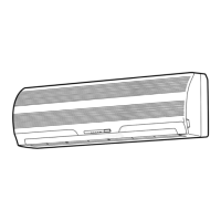
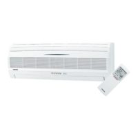
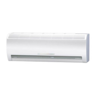
Indoor unit
44
44
4 Room temperature sensor
55
55
5 Front panel
66
66
6 Air inlet grille
77
77
7 Air filter
88
88
8 Air outlet
99
99
9 Horizontal air flow louver
!!
!!
! Vertical air flow louver
""
""
" Display panel
##
##
# Infrared signal receiver
$$
$$
$ Remote control
Display panel
The operating conditions are indicated below.
11
11
1 TEMPORARY button
22
22
2 Hi POWER lamp (Green)
33
33
3 FILTER lamp (Orange)
44
44
4 PRE. DEF lamp (Orange)
55
55
5 TIMER lamp (Yellow)
66
66
6 OPERATION lamp (Green/*Orange)
The operation lamps flash rapidly (five times per second),
when safety protection features come into operation.
* When the auto restart function is in operation, the
OPERATION lamp is orange.
TEMPORARY button
If you misplace or lose the remote control or its batteries are
exhausted, push the TEMPORARY button.
• Push the TEMPORARY button to start the air conditioner.
• Push this button once again to stop it.
(24 class)(18 class)
NAMES AND FUNCTIONS OF INDICATORS AND CONTROLS
ON INDOOR UNIT
1
3
2
PRE.DEF TIMER OPERATIONFILTERHi POWER
2 31 4 5 6
 Loading...