Do you have a question about the Toshiba RAS-24UAH-E-1 and is the answer not in the manual?
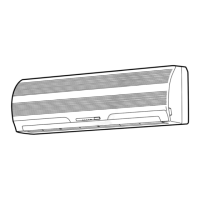
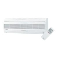
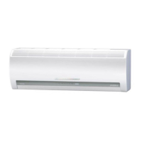
Detailed construction views and dimensions of the indoor unit.
Construction views and dimensions for various outdoor unit models.
Wiring diagram for specific indoor/outdoor unit models.
Wiring diagram for specific indoor/outdoor unit models.
Wiring diagram for specific indoor/outdoor unit models.
Wiring diagram for specific indoor/outdoor unit models.
Wiring diagram for specific indoor/outdoor unit models.
Wiring diagram for specific indoor/outdoor unit models.
Wiring diagram for specific indoor/outdoor unit models.
Wiring diagram for specific indoor/outdoor unit models.
Specifications for electrical components of indoor units.
Specifications for electrical components of outdoor units.
Refrigeration cycle diagram and operating conditions.
Refrigeration cycle diagram and operating conditions.
Refrigeration cycle diagram and operating conditions.
Refrigeration cycle diagram and operating conditions.
Refrigeration cycle diagram and operating conditions.
Refrigeration cycle diagram and operating conditions.
Refrigeration cycle diagram and operating conditions.
Refrigeration cycle diagram and operating conditions.
Control block diagram for specific indoor unit models.
Control block diagram covering various indoor/outdoor unit models.
Overview of how the air conditioner is controlled.
Description of vertical air flow louver operation and settings.
Details on the indoor fan motor's speed control.
Explanation of the operational control circuits.
How the unit operates in fan-only mode.
Control logic for cooling mode operation.
Control logic for dry mode operation.
Control logic for heating mode operation (Heat pump models).
How automatic operation selects modes based on temperature.
Operation details when the Hi POWER mode is activated.
Control to prevent excessive refrigerating cycle pressure.
Control to prevent indoor heat exchanger freezing.
Procedure for defrost operation in heating mode.
Functionality and setting of the auto restart feature.
Step-by-step guide to enable the auto restart function.
Instructions to disable the auto restart function.
Effect of power failure on timer operations.
Indicator for filter maintenance and how to reset it.
Procedure to reset the filter check lamp indicator.
Important safety precautions for installation.
Diagrams showing placement and connections for installation.
General installation steps and considerations.
List and description of optional parts for installation.
Inventory of included accessories and installation components.
Detailed procedures for installing the indoor unit.
Guidelines for selecting the optimal installation location for the indoor unit.
Steps for preparing the wall and mounting the installation plate.
Procedures and precautions for electrical connections.
Instructions for connecting the indoor and outdoor unit wiring.
Guidance on connecting refrigerant pipes and drain hoses.
Steps for securely mounting the indoor unit to the installation plate.
Ensuring proper drainage for the indoor unit.
General procedures for installing the outdoor unit.
Guidelines for selecting the optimal installation location for the outdoor unit.
Detailed steps for connecting refrigerant pipes.
Procedure for evacuating the system using a vacuum pump.
Instructions for connecting the outdoor unit's wiring.
Guide to setting the remote control selector switch for multiple units.
Miscellaneous installation procedures like gas leak testing.
Procedure for checking for refrigerant gas leaks.
How to perform a test run of the air conditioner.
Information and setting for the auto restart function.
General steps for troubleshooting issues.
Fundamental checks before diagnosing problems.
Verifying the main power supply voltage.
Ensuring correct connection of cables between units.
Verifying the microcontroller's control logic.
Initial assessment of the unit's condition based on symptoms.
Functions and responsibilities of the indoor unit controller.
How the unit diagnoses and indicates failures.
Using the remote control for system self-diagnosis.
Steps to enter and use the remote control's service mode.
Diagnostic flowcharts for identifying faulty components.
Specific troubleshooting steps for indoor unit issues.
Troubleshooting steps when the indoor unit does not operate.
Diagnosing issues when the indoor fan motor does not work.
Troubleshooting when the indoor fan motor rotates automatically.
Diagnosing issues when the compressor fails to operate.
Troubleshooting issues related to interconnect and signal wires.
Steps for troubleshooting when the outdoor unit is inactive.
Diagnosing why the outdoor unit stops shortly after operation.
Steps for checking and troubleshooting the P.C. board.
Procedure for inspecting the indoor unit's P.C. board.
Procedure to adjust the restart delay timer duration.
Diagrams showing the layout of components on the P.C. board.
Steps to diagnose and resolve remote control issues.
Procedures for replacing parts of the indoor unit.
Procedures for replacing parts of specific outdoor unit models.
Exploded view and parts list for indoor unit electrical components.
Exploded view and parts list for the indoor unit.
Exploded view and parts list for the RAS-24UAH-E-1 outdoor unit.
Exploded view and parts list for the RAS-18UAH-E2 outdoor unit.
Exploded view and parts list for multiple outdoor unit models.
Exploded view and parts list for the RAS-18UAX2 outdoor unit.
Exploded view and parts list for the RAS-18UA-AR2 outdoor unit.
| Brand | Toshiba |
|---|---|
| Model | RAS-24UAH-E-1 |
| Category | Air Conditioner |
| Language | English |