Do you have a question about the Toshiba RAS-4M27YACV-E and is the answer not in the manual?
Detailed technical specifications for indoor and outdoor units, including electrical and performance data.
Performance data when different indoor units are combined with a specific outdoor unit.
Curves showing current vs. inverter output frequency for cooling and heating operations.
Graphs illustrating how cooling and heating capacity vary with outdoor temperature.
Graphs showing how cooling and heating capacity change based on total pipe length.
Electrical data for the outdoor unit (RAS-4M27YAV-E) during cooling operation.
Crucial safety precautions for handling R410A refrigerant during installation and servicing.
Guidelines for installing refrigerant piping, including materials and joint specifications.
Lists tools exclusive for R410A and general tools required for installation and servicing.
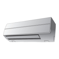
Exploded view and dimensions of the indoor unit, showing major components.
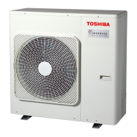
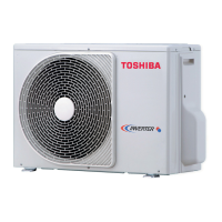
Exploded view and dimensions of the outdoor unit, detailing components and their placement.
Detailed wiring diagram for the indoor unit, including fault diagnosis points.
Detailed wiring diagram for the outdoor unit, showing component connections.
List of electrical parts for the indoor unit with their specifications.
List of electrical parts for the outdoor unit with their specifications.
Table of operation data for cooling mode with RAS-4M27YAV-E.
Block diagram of the indoor unit's control system, including MCU functions.
Block diagram of the outdoor unit's control system, including inverter and sensors.
Overview of the air conditioner's operation, including DC motors and compressor control.
Step-by-step instructions on how to enable and configure the automatic restart feature.
Instructions for disabling the auto restart function and its behavior during power failure.
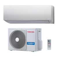
Identification and explanation of the buttons and indicators on the remote controller.
Essential safety precautions and warnings for installing the air conditioner.
Procedures for installing the indoor unit, including accessories and mounting.
Guidance on selecting an appropriate location for installing the indoor unit.
Instructions for cutting wall openings and mounting the indoor unit installation plate.
Detailed steps for connecting the inter-unit wiring, including precautions.
Procedures for installing piping and drain hoses, covering routing and insulation.
Instructions for proper drain hose installation to ensure effective water drainage.
Steps for securely attaching the indoor unit to the wall mounting plate.
Guidelines for installing the outdoor unit, including parts and placement.
Specifics on refrigerant piping kits and materials required for the conventional refrigerant.
Recommendations for choosing a suitable location for the outdoor unit, considering wind and noise.
Detailed instructions for connecting refrigerant piping, including flaring.
Initial checks for troubleshooting, including power supply and voltage confirmation.
Basic troubleshooting steps, including LED flashing and remote controller self-diagnosis.
Guide to interpreting indoor unit LED indicators for self-diagnosis.
Procedure for using the remote controller to perform self-diagnosis and interpret check codes.
Troubleshooting guide for indoor unit issues based on symptoms like no power or fan issues.
Diagnosis steps for wiring failures affecting outdoor unit operation or stopping after startup.
Flowchart for diagnosing inverter assembly troubles in the outdoor unit.
Procedures for checking the indoor unit's P.C. board for defects.
Diagram showing the layout of components on the indoor unit's main P.C. board.
Checking procedures for specific indoor unit parts like sensors and motors.
Checking procedures for outdoor unit components like compressor and fan motor.
Step-by-step instructions for replacing major parts of the indoor unit.
Procedure for replacing the microcomputer and P.C. board layout.
Steps for detaching major components of the outdoor unit for replacement.
Exploded view and parts list for indoor unit component group 1.
Exploded view and parts list for indoor unit component group 2.
Exploded view and parts list for the outdoor unit.
Diagram showing the layout of components on the P.C. board for the RAS-4M27YAV-E.
| Brand | Toshiba |
|---|---|
| Model | RAS-4M27YACV-E |
| Category | Air Conditioner |
| Language | English |