Do you have a question about the Toshiba RAS-4M27YAV-E and is the answer not in the manual?
Detailed performance and electrical specifications for the air conditioner units.
Performance data for multi-unit configurations with specific outdoor units.
Comprehensive electrical specifications and data for outdoor units, including current and voltage ratings.
Crucial safety precautions and guidelines for handling R410A refrigerant during installation and servicing.
Detailed instructions on material selection and processing for R410A refrigerant piping installation.
Lists and descriptions of specialized tools required for R410A refrigerant handling and installation.
Exploded diagrams and dimensions for the indoor unit components.
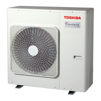
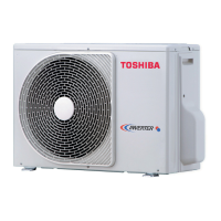
Exploded diagrams and dimensions for the outdoor unit components.
Detailed wiring diagram for the indoor unit, including component connections and fault checking.
Detailed wiring diagram for the outdoor unit, showing component connections and system layout.
List of electrical parts for the indoor unit with their specifications and types.
List of electrical parts for the outdoor unit, including model names and ratings.
Performance data for cooling operation under various temperature and operating conditions.
Block diagram showing the control functions and signal flow within the indoor unit.
Block diagram illustrating the control logic and components of the outdoor unit's inverter assembly.
Overview of the air conditioner's control system, including indoor and outdoor unit roles.
Detailed explanations of various operating modes like COOL, DRY, and FAN only.
Instructions for using temporary operation modes like Auto and Cooling.
Explanation and setup procedure for the automatic restart feature after power interruptions.
Details on the parts and indications of the remote controller for operation.
Critical safety warnings and precautions to be followed during the installation process.
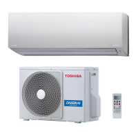
Step-by-step guide for the installation of the indoor unit, including mounting and piping.
Guidelines for installing the outdoor unit, including placement, piping, and precautions.
Initial troubleshooting steps including power and voltage checks for the air conditioner.
Basic fault diagnosis methods, including LED indicators and symptom checks.
Interpretation of indoor unit LED indicators for self-diagnosis and error identification.
Procedure for performing self-diagnosis using the remote controller and interpreting check codes.
Troubleshooting guide based on symptoms, focusing on the indoor unit and power issues.
Explanation of outdoor unit LED indicators for self-diagnosis and fault identification.
Step-by-step diagnostic flowchart for troubleshooting the outdoor unit's inverter assembly.
Procedures for checking the functionality of main internal components like P.C. boards and motors.
Specific method to test the outdoor fan motor's condition using resistance measurements.
Detailed instructions for replacing key components of the indoor unit, including front panel and PC boards.
Procedure for accessing and replacing the microcomputer on the indoor unit's PC board.
Procedures for disassembling and replacing parts of the outdoor unit, including panels and inverter assembly.
Exploded view and parts list for the indoor unit's primary components.
Exploded view and parts list for the outdoor unit, detailing various components.
| Brand | Toshiba |
|---|---|
| Model | RAS-4M27YAV-E |
| Category | Air Conditioner |
| Language | English |