Do you have a question about the Toshiba RAS-4M23SAV-E and is the answer not in the manual?
Precautions for new R410A refrigerant, power disconnection, and high voltage.
Warnings about combustible gases, heat sources, refrigerant mixing, and electrical safety.
Safety precautions for handling R410A refrigerant, tools, and potential hazards.
Details on piping materials, joints, and processing for R410A refrigerant systems.
Diagram illustrating the refrigerant flow between indoor and outdoor units.
Explanation of capacity control, release control, and protective functions.
General safety warnings and precautions before starting installation.
Procedures for installing the indoor unit, including location and mounting.
Guidelines for installing the outdoor unit, including placement and precautions.
Steps and precautions for connecting refrigerant piping, including flaring and tightening.
Procedure for evacuating air from the refrigerant system using a vacuum pump.
Instructions for electrical work, wiring connections, and power cord installation.
Using a leak detector for R410A and performing leak checks on connections.
Procedure to check for wiring and piping errors using LEDs and connectors.
Index of troubleshooting procedures and notes on discharging capacitors.
How to use the remote controller's service mode for self-diagnosis and check codes.
Diagnosing inverter assembly issues, fan motor, and compressor problems.
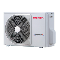
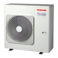
| Type | Air conditioner outdoor unit |
|---|---|
| Ionizer | - |
| Multi-split | Yes |
| Product color | White |
| Compressor type | Rotary |
| Built-in display | No |
| Air conditioner functions | Cooling, Heating |
| Cooling capacity in watts (max) | 7500 W |
| Cooling capacity in watts (min) | 1400 W |
| Heating capacity in watts (max) | 8400 W |
| Cooling capacity in watts (nominal) | 6800 W |
| Cooling energy efficiency (EER, W/W) | 3.49 |
| Heating energy efficiency (COP, W/W) | 4.42 |
| Operating temperature (cooling) (T-T) | 5 - 43 °C |
| Operating temperature (heating) (T-T) | -15 - 24 °C |
| Heating capacity in watts (nominal) (Average heating season) | 7200 W |
| Energy efficiency class (cooling) | A |
| Power consumption (cooling) (max) | 1950 W |
| Power consumption (cooling) (min) | - W |
| Power consumption (heating) (max) | 1630 W |
| Hourly energy consumption (cooling) | - kWh |
| Indoor unit width | - mm |
| Indoor units quantity | 0 |
| Outdoor unit depth | 320 mm |
| Outdoor unit width | 900 mm |
| Outdoor unit height | 795 mm |
| Outdoor unit weight | 55000 g |
| Outdoor units quantity | 1 |
| Outdoor unit noise level | 63 dB |
| Cooling airflow (outdoor unit) | 2802 m³/h |


