Do you have a question about the Toshiba RAS-M10SKV-E and is the answer not in the manual?
Essential safety precautions for general use and servicing.
Specific safety measures for handling R410A refrigerant during installation and servicing.
Highlights electrical hazards, high voltage warnings, and connection safety.
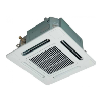
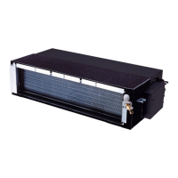
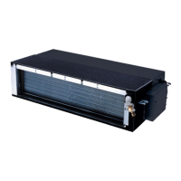
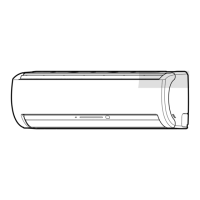
Details compatibility of outdoor units with indoor models for different types.
Comprehensive specifications for indoor units including dimensions, performance, and noise levels.
Crucial safety measures, installation guidelines, and tools for R410A refrigerant.
Procedures for refrigerant recharging and pipe brazing techniques.
Exploded view and dimensions of the indoor unit showing component placement.
Detailed schematic illustrating the electrical interconnections between indoor and outdoor units.
Lists and specifies electrical parts within the indoor unit, like motors and sensors.
A visual representation of the refrigerant circuit, its components, and flow direction.
Diagram showing how the indoor unit processes signals and controls its functions.
Illustrates the signal flow from the remote control to the indoor unit.
Explains the roles of indoor/outdoor controllers and communication protocols.
Covers basic operation, mode selections, special functions, and fan control.
Details the usage and display indicators of the remote control unit.
Guidelines for selecting an installation location and a general installation diagram.
Procedures for mounting the indoor unit, performing electrical work, and wiring.
Steps for installing refrigerant piping and ensuring proper drain hose setup.
Basic checks before diagnosing faults, including power and normal operations.
Interpreting LED flashing patterns on the indoor unit for fault diagnosis.
Guide to using the remote control for self-diagnosis and check code interpretation.
A systematic approach to diagnosing issues based on observable symptoms.
Detailed instructions for removing and replacing major parts of the indoor unit.
Procedures for accessing and replacing the microcomputer and associated circuit boards.
Visual breakdown of the indoor unit showing all parts and their reference numbers.
| Brand | Toshiba |
|---|---|
| Model | RAS-M10SKV-E |
| Category | Air Conditioner |
| Language | English |