EasyManua.ls Logo

Toshiba RAS-M10YKCV-E User Manual

Toshiba RAS-M10YKCV-E
125 pages
To Next Page IconTo Next Page
Page #1 background imageLoading...
Page #1 background image
SERVICE MANUAL
FILE NO. A01-004
AIR-CONDITIONER
SUPPLEMENT
SPLIT TYPE
PRINTED IN JAPAN, Mar.,2001 ToMo
RAS-M10YKV-E, RAS-M13YKV-E, RAS-M16YKV-E
RAS-4M27YAV-E
RAS-M10YKCV-E, RAS-M13YKCV-E, RAS-M16YKCV-E
RAS-4M27YACV-E
RAS-M10YKV-E, RAS-M13YKV-E, RAS-M16YKV-E
RAS-3M26YAV-E
R410A
• Indoor Unit (1)
• Indoor Unit (2)
• Outdoor Unit
• P.C. board Layout
RAS-4M27YAV-E
RAS-4M27YACV-E
RAS-3M26YAV-E
Parts List
File No. A01-004
Question and Answer IconNeed help?

Do you have a question about the Toshiba RAS-M10YKCV-E and is the answer not in the manual?

Toshiba RAS-M10YKCV-E Specifications

General IconGeneral
BrandToshiba
ModelRAS-M10YKCV-E
CategoryAir Conditioner
LanguageEnglish

Summary

SERVICE MANUAL

Parts List

List of replaceable parts for the air conditioner.

1. SPECIFICATIONS

1-1. Specifications

Core operational and physical specifications of the air conditioner.

3. CONSTRUCTION VIEWS

3-1. Indoor Unit

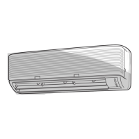
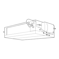
Exploded view and dimensions of the indoor unit.

3-2. Outdoor Unit

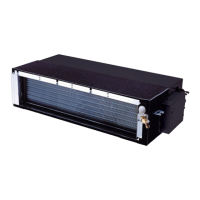
Exploded view and dimensions of the outdoor unit.

4. WIRING DIAGRAM

4-1. Indoor Unit Wiring

Detailed wiring diagram for the indoor unit.

4-2. Outdoor Unit Wiring

Detailed wiring diagram for the outdoor unit.

5. SPECIFICATIONS OF ELECTRICAL PARTS

5-1. Indoor Unit Electrical Parts

Electrical parts specific to the indoor unit.

5-2. Outdoor Unit Electrical Parts

Electrical parts specific to the outdoor unit.

6. REFRIGERANT CYCLE DIAGRAM

Refrigerant Cycle Details

Specific refrigerant cycle diagrams for different unit combinations.

6-1. Operation Data

Cooling Operation Data

Operation data for cooling mode across different units and voltages.

Heating Operation Data

Operation data for heating mode across different units and voltages.

7. CONTROL BLOCK DIAGRAM

7-1. Indoor Unit Control Block Diagram

Control logic for the indoor unit.

7-2. Outdoor Unit Control Block Diagram

Control logic for the outdoor unit.

8. OPERATION DESCRIPTION

8-1. Outline of Air Conditioner Control

Overview of the air conditioner's control system.

8-2. Description of Operation Circuit

Details on various operating modes like Cooling, Dry, and Heating.

8-3. Temporary Operation

Features for temporary auto and cooling operations.

8-4. Auto Restart Function

Automatic unit restart after power interruption.

8-5. Remote Controller Functions

Explanation of remote controller parts and indications.

9. INSTALLATION PROCEDURE

9-1. Safety Cautions

Essential safety precautions during installation.

9-2. Indoor Unit Installation

Procedures for installing the indoor unit.

9-3. Outdoor Unit Installation

Procedures for installing the outdoor unit.

10. HOW TO DIAGNOSE THE TROUBLE

10-1. Initial Checks and Primary Judgment

Basic troubleshooting steps and initial problem assessment.

10-3. Indoor Unit LED Diagnostics

Interpreting indoor unit LED indicators for fault diagnosis.

10-4. Remote Controller Self-Diagnosis

Using the remote controller for self-diagnosis of unit faults.

10-5. Symptom-Based Troubleshooting

Diagnosing problems based on observed symptoms and wiring issues.

10-6. Outdoor Unit LED Diagnostics

Interpreting outdoor unit LED indicators for fault diagnosis.

10-8. Checking Main Parts

Procedures for checking key internal components like P.C. boards and sensors.

10-9. Outdoor Fan Motor Check

Method to determine if the outdoor fan motor is functioning correctly.

11. HOW TO REPLACE THE MAIN PARTS

11-1. Indoor Unit Parts Replacement

Steps for replacing parts of the indoor unit.

11-3. Outdoor Unit Parts Replacement

Steps for replacing parts of the outdoor unit.

12. EXPLODED VIEWS AND PARTS LIST

12-1. Indoor Unit Exploded Views and Parts List

Detailed exploded views and parts lists for indoor units.

12-2. Outdoor Unit Exploded Views and Parts List

Detailed exploded views and parts lists for outdoor units.

12.3. P.C. Board Layouts

Layout diagrams of the Printed Circuit Boards for various models.

Related product manuals