Do you have a question about the Toshiba RAS-M10UKCV-E3 and is the answer not in the manual?
Details core specifications for various models, including capacity, power, and noise.
Lists performance data for various indoor/outdoor unit combinations, covering capacity and power.
Provides detailed electrical specifications for outdoor units, including power supply and current ratings.
Outlines critical safety measures for handling R410A refrigerant during installation and servicing.
Covers requirements for refrigerant piping materials, joints, and processing for R410A systems.
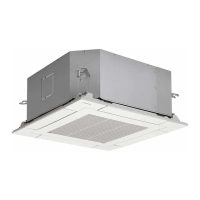
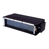
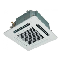
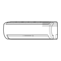
Provides dimensional drawings and component views of the indoor air conditioning unit.
Presents dimensional drawings and component layouts for the outdoor unit of the air conditioner.
Illustrates the electrical connections and component layout for the indoor unit's wiring.
Details the wiring diagram for the outdoor unit's inverter assembly, showing component interconnections.
Lists and specifies electrical components used in the indoor unit, including motors, sensors, and boards.
Details the electrical parts used in the outdoor unit, such as compressors, fans, relays, and sensors.
Presents cooling operation data based on temperature conditions, showing unit combinations and performance metrics.
Shows the functional blocks and signal flow for the indoor unit's control system.
Illustrates the control logic and component interactions within the outdoor unit's inverter assembly.
Explains the overall control strategy, including roles of indoor/outdoor controllers and compressor operation.
Describes how compressor motor speed is adjusted to control cooling capacity via an inverter.
Details how the system prevents indoor heat exchanger freezing by adjusting compressor speed.
Explains the automatic and manual control of vertical air flow louvers.
Describes the non-step variable DC motor control for the indoor fan speed.
Covers the process and control logic for the air conditioner's cooling mode.
Explains the dehumidifying-priority operation, including fan and compressor speed control.
Details the operation logic for heating mode, including fan speed control and defrost prevention.
Describes the automatic selection of operating modes based on ambient conditions.
Explains temporary auto and cooling operations, including start/stop procedures.
Details how the unit restarts automatically after a power supply interruption.
Explains the functions and operation of the remote control unit.
Provides critical safety warnings and precautions for the installation of the air conditioner.
Lists required tools for R410A installation and servicing, highlighting differences from R22 tools.
Details the steps for installing the indoor unit, including mounting and piping.
Specifies suitable and unsuitable locations for indoor unit installation, considering space and environment.
Guides on creating openings and securely mounting the indoor unit's installation plate.
Covers the electrical connections and power supply requirements for the indoor unit installation.
Explains how to connect the wiring between the indoor unit and the outdoor unit.
Details how to form and install refrigerant pipes and the drain hose for proper unit function.
Provides instructions on ensuring proper drainage for the indoor unit to prevent water issues.
Explains how to set the remote controller selector switch for multi-room installations.
Outlines the final checks and test operations to ensure proper installation and function.
Covers the installation requirements and considerations for the outdoor unit.
Lists the accessory and installation parts provided with the outdoor unit.
Specifies requirements for refrigerant piping materials and connections, emphasizing R410A compatibility.
Defines suitable and unsuitable locations for outdoor unit installation, considering wind and noise.
Lists optional parts available locally for installation purposes.
Lists optional parts available separately, such as reducers and expanders.
Details the procedures for connecting refrigerant pipes, including flaring and tightening.
Provides general installation guidelines for the outdoor unit, including clearance and fixing.
Explains the process of evacuating the air and moisture from the refrigerant circuit using a vacuum pump.
Covers connecting the power cord and wiring for the outdoor unit.
Describes initial steps to confirm power supply and voltage before proceeding with detailed diagnosis.
Outlines initial diagnostic methods, including LED status and remote control self-diagnosis.
Explains how to interpret flashing LEDs on the indoor unit for fault diagnosis.
Details how to use the remote control's service mode to retrieve error codes for diagnosis.
Provides step-by-step instructions for operating the remote control in service mode.
Offers essential precautions to be taken during servicing and troubleshooting procedures.
Guides diagnosis based on specific symptoms, including power issues and motor operation.
Addresses troubleshooting for wiring faults between indoor and outdoor units, including signal issues.
Explains how to diagnose outdoor unit faults using the status of LEDs on the sub-control board.
Provides a flowchart for diagnosing issues within the outdoor unit's inverter assembly.
Offers simple methods to check the functionality of key components like P.C. boards and motors.
Details inspection procedures for the indoor unit's main and indication P.C. boards.
Describes how to check specific indoor unit components like sensors and motors for proper function.
Explains how to test outdoor unit components such as the compressor, fan motor, and sensors.
Provides methods for checking specific electronic parts like capacitors, converter modules, and IGBT modules.
Offers a straightforward method to determine if the outdoor fan motor is functioning correctly.
Details the procedures for replacing main components of the indoor unit, such as the front panel and electrical parts.
Describes the steps for replacing the microcomputer on the indoor unit.
Outlines the procedures for detaching and replacing major components of the outdoor unit.
Presents an exploded view and a parts list for the indoor unit components.
Provides an exploded view and a parts list for the outdoor unit components.
Shows the layout of components on the P.C. boards for the outdoor unit.
| Brand | Toshiba |
|---|---|
| Model | RAS-M10UKCV-E3 |
| Category | Air Conditioner |
| Language | English |