Do you have a question about the Toshiba RAS-M10NKV-E and is the answer not in the manual?
Details specific technical parameters for NKV-E and NKCV-E model series.
Shows the detailed wiring connections for indoor units, distinguishing between 10/13k and 16k models.
Diagrams the MCU functions, sensors, and communication pathways for the indoor unit's operation.
Details operational controls like capacity, sensors, fan, and louvers for optimal performance.
Covers remote control functions, buttons, and their operations.
Provides essential safety guidelines and precautions for installing the air conditioner unit.
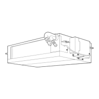
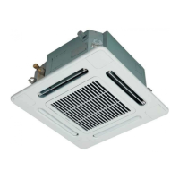
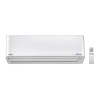
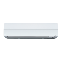
Details the steps and diagrams for installing the indoor unit, including piping and wiring.
Covers initial checks of power supply, voltage, and common operational scenarios that are not faults.
Provides a step-by-step troubleshooting guide based on symptoms for indoor unit issues.
| Cooling Capacity | 2.5 kW |
|---|---|
| Heating Capacity | 3.2 kW |
| EER | 3.21 |
| COP | 3.61 |
| Refrigerant | R410A |
| Power Supply | 220-240V, 50Hz |
| Indoor Unit Dimensions (W x H x D) | 798 x 293 x 230 mm |
| Outdoor Unit Dimensions (W x H x D) | 660 x 530 x 240 mm |
| Indoor Unit Weight | 9 kg |
| Outdoor Unit Weight | 23 kg |
| Type | Split Type |
| Noise Level (Outdoor Unit) | 49 dB |