EasyManua.ls Logo

Toshiba RAS-M10YKV-E User Manual

Toshiba RAS-M10YKV-E
125 pages
To Next Page IconTo Next Page
Page #1 background imageLoading...
Page #1 background image
SERVICE MANUAL
FILE NO. A01-004
AIR-CONDITIONER
SUPPLEMENT
SPLIT TYPE
PRINTED IN JAPAN, Mar.,2001 ToMo
RAS-M10YKV-E, RAS-M13YKV-E, RAS-M16YKV-E
RAS-4M27YAV-E
RAS-M10YKCV-E, RAS-M13YKCV-E, RAS-M16YKCV-E
RAS-4M27YACV-E
RAS-M10YKV-E, RAS-M13YKV-E, RAS-M16YKV-E
RAS-3M26YAV-E
R410A
• Indoor Unit (1)
• Indoor Unit (2)
• Outdoor Unit
• P.C. board Layout
RAS-4M27YAV-E
RAS-4M27YACV-E
RAS-3M26YAV-E
Parts List
File No. A01-004
Question and Answer IconNeed help?

Do you have a question about the Toshiba RAS-M10YKV-E and is the answer not in the manual?

Toshiba RAS-M10YKV-E Specifications

General IconGeneral
TypeSplit System
Cooling Capacity2.5 kW
Heating Capacity3.2 kW
RefrigerantR32
Power Supply220-240V, 50Hz
Indoor Unit Dimensions (W x H x D)798 x 293 x 230 mm
Outdoor Unit Dimensions (W x H x D)660 x 530 x 240 mm
Indoor Unit Weight9 kg
Noise Level (Outdoor)49 dB(A)

Summary

Service Manual - Air Conditioner Split Type

1. Specifications

1-1. Specifications

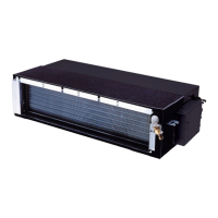
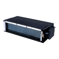
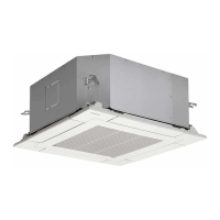
Detailed technical specifications for various indoor and outdoor units, including cooling/heating capacity, power, noise, dimensions, and piping.

1-3. Electrical Data

2. Refrigerant R410A

2-1. Safety During Installation and Servicing

Outlines crucial safety precautions and considerations when installing or servicing air conditioners using R410A refrigerant.

2-3. Tools

4. Wiring Diagram

4-1. Indoor Unit

Provides the detailed wiring diagram for the indoor unit, including connections and component labels.

5. Specifications of Electrical Parts

6. Refrigerant Cycle Diagram

7. Control Block Diagram

8. Operation Description

8-1. Outline of Air Conditioner Control

Provides an overview of the air conditioner's operation, control logic, and component functions.

8-1-1. Capacity Control

Explains how cooling capacity is regulated by adjusting compressor motor speed via the inverter.

9. Installation Procedure

9-1. Safety Cautions

Provides critical safety warnings and guidelines for installing the air conditioner unit and its components.

10. How to Diagnose the Trouble

10-2. Primary Judgment

Guides on initial troubleshooting steps, including checking power, primary judgments, and symptom analysis.

10-3. Judgment by Flashing LED of Indoor Unit

Explains how to interpret indoor unit LED indicators for self-diagnosis of faults.

10-4. Self-Diagnosis by Remote Controller (Check Code)

Details the process of performing self-diagnosis using the remote controller's check code function.

10-5. Judgment of Trouble by Every Symptom

Provides guidance on diagnosing troubles based on observed symptoms and unit behavior.

10-6. Trouble Diagnosis by Outdoor LED

10-7. How to Diagnose Trouble in Outdoor Unit

10-7-1. Summarized Inner Diagnosis of Inverter Assembly

Offers a summarized diagnostic process for the outdoor unit's inverter assembly.

10-8. How to Check Simply the Main Parts

10-9. How to Simply Judge Whether Outdoor Fan Motor is Good or Bad

11. How to Replace the Main Parts

11-1. Indoor Unit

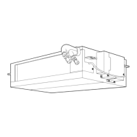
Provides step-by-step instructions for replacing main parts of the indoor unit.

Related product manuals