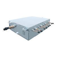
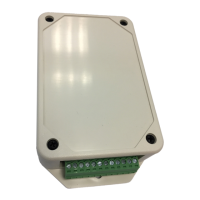
LC DX Interface wiring
Temperature sensors
The refrigerant temperature sensors are inserted into the brazed sensor holders and secured using the supplied FIX-
PLATE.
The sensor cables are to be connected as follows:
TC Sensor BLACK 2-pin plug to BLACK 2-pin socket
TCJ Sensor RED 2-pin plug to RED 2-pin socket
TA Resin Bulb Sensor YELLOW 2-pin plug to Yellow 2-pin socket
The sensor cables cannot be extended or shortened, they are supplied at the maximum permissible length of 5m.
Please coil excess length within AHU.
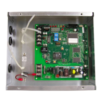
Inter-unit Connecting wire
Terminal ⏚/1 / 2 / 3 on the LC DX Interface should be connected to the corresponding terminals on the outdoor unit.
External On / Off
Terminal 4 / 5 External On / Off input (230V AC) to relay coil (KP4). When the relay is energised, the system is
switched on. When the relay is not energised, the system is switched off. If the system is switched using external On /
Off, then switching on / off using the remote control is still possible (On / Off is locked to last instruction).
Fan motor output (230V AC)
Terminal 6 / 7 Fan motor output 230V AC (3A Max.) controlled by system. The fan operation will stop during defrosting
and at the start of heating operation (Cold draft prevention). Please contact your local sales support if you want to fan
operation to be continuous.
Remote control BUS line (A/B)
Terminal A / B at these terminals an optional remote controller can be attached.
Fan operation Output
Terminal 8 / 9 during operation of the fan the dry contact between 8/9 is closed (Rating: 250VAC 8A). The fan
operation will stop during defrosting and at the start of heating operation (Cold draft prevention). Please contact your
local sales support if you want to fan operation to be continuous.
Alarm signal from the ventilation kit
Terminal 10 / 11 if there is an error at the system, this is indicated with a dry normally open contact at this terminal
(Rating: 250VAC 8A).
Fan Error Input
Terminal 12 / 13 an operation monitor (supplied locally), of the external fan is to be attached at this terminal as a dry
contact (for instance, differential pressure monitor, vane relay or similar). A closed contact generates the error
message L30 (Rating: 12VDC).
External safety contact
Terminal 14/15 If this contact is open for more than 1 minute, the error message P10 is generated and the system
switches off automatically. This contact can, for instance, be used with an onsite frost protection monitor (Rating:
12VDC).
If the External safety contact is not used, then the contact should be bridged.
 Loading...