Each time you push button, indoor unit
numbers in the control group change cyclically.
Select the indoor unit you want to change settings for.
The fan of the selected unit runs and the louvers start
swinging. You can confirm the indoor unit for which
you want to change settings.
Procedure 3
Using “TEMP”,
buttons, specify CODE NO.
[
].
Procedure 4
Using timer “TIME”
buttons, select SET
DATA [
].
Push button. When the display changes from
flashing to lit, the setup is completed.
• To change settings of another indoor unit, repeat
from procedure 2.
• To change other settings of the selected indoor unit,
repeat from procedure 3.
Use
button to clear the settings.
To make settings after
button was pushed,
repeat from procedure 2.
Procedure 6
When settings have been completed, push
button
to determine the settings.
When
button is pushed, flashes and then
the display content disappears and the air conditioner
enters the normal stop mode.
(While
is flashing, no operation of the remote
controller is accepted).
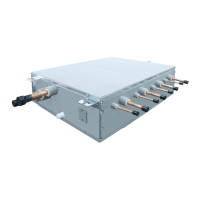
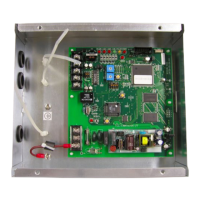
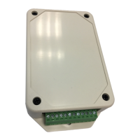
The circuit board of the ventilation kit is not preconfigured at delivery. Some parameters must be set using the DN code
menu.
Follow to the basic operation procedure (1 → 2 → 3 → 4 → 5 → 6).
DN
CODE
OUTDOOR MODEL (RAV-****-E)
11 CAPACITY CODE
0009 0012 0015 0017 0018 0021 0023
01
DIRTY FILTER ALARM
(Disabled)
0000 (Default 0002)
03
CENTRAL CONTROL ADDRESS
(Unset)
0099* Default
0d
0000** Default
0001**
0f
AVAILABLE MODE
(Heat Pump)
0000** Default
(Cooling Only)
0001**
10
0006 (Default 0000)
12
0099* Default
13
0099* Default
14
0099* Default
28
AUTOMATIC RESTART
(Enabled)
0001 (Default 0000 Disabled)
* 0099 = address not assigned (system addresses are assigned during the automatic addressing by the system.
Central addresses can be assigned automatically with a central remote control or manually. Subsequent
modifications may lead to malfunction.)
** AUTO MODE Enabled / Disabled and HEAT PUMP / COOLING ONLY are automatically selected by the
connecting Outdoor unit.
LC DX Interface Configuration
 Loading...