Do you have a question about the Toshiba RAV-SM1101AT-E and is the answer not in the manual?
Safety precautions for handling R410A refrigerant during installation and servicing.
Details on copper pipes and joints suitable for R410A refrigerant installation.
Specific tools needed for R410A installation, including exclusive and general tools.
Step-by-step procedure for recharging refrigerant into the system.
Covers materials, flux, and methods for brazing refrigerant pipes.
Details of the print circuit board and its components for outdoor unit control.
Explains the functions of PMV control, temperature release, and current release controls.
General guidelines for troubleshooting wired remote controller types.
Lists error codes detected by the indoor unit, their causes, and measures.
Method to judge outdoor unit errors using LED displays and dip switches.
Details the mapping between check codes and LED display patterns for error identification.
Flowcharts providing step-by-step troubleshooting for specific check codes.
Procedures for detaching and attaching valve cover, wiring cover, and upper cabinet.
Procedures for detaching and attaching the front cabinet.
Procedures for detaching and attaching the inverter assembly.
Procedures for detaching and attaching the control P.C. board assembly.
Procedures for detaching and attaching the fan motor.
Procedures for detaching and attaching the compressor and reactor.
Procedures for detaching and attaching the PMV coil and fan guard.
Procedures for removing and attaching front panel and ceiling plate.
Procedures for detaching and attaching discharge port and side cabinets.
Procedures for detaching and attaching the inverter assembly for specific models.
Procedures for detaching and attaching the cycle P.C. board.
Procedures for detaching and attaching the IPDU P.C. board.
Procedures for detaching and attaching the fan motor for specific models.
Procedures for detaching and attaching compressor and PMV coil for specific models.
Procedures for detaching and attaching the fan guard for specific models.
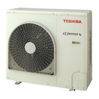
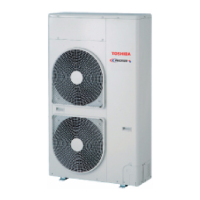
| Brand | Toshiba |
|---|---|
| Model | RAV-SM1101AT-E |
| Category | Air Conditioner |
| Language | English |




 Loading...