EasyManua.ls Logo

Toshiba RAV-SM1102CT-E User Manual

Toshiba RAV-SM1102CT-E
196 pages
To Next Page IconTo Next Page
Page #1 background imageLoading...
Page #1 background image
R410A
FILE NO. A05-018
Revised : Nov. 2006
SERVICE MANUAL/INTEGRATION
AIR-CONDITIONER
SPLIT TYPE
INDOOR UNIT
<DIGITAL INVERTER>
RAV-SM562UT-E RAV-SM562BT-E RAV-SM562CT-E
RAV-SM802UT-E RAV-SM802BT-E RAV-SM802CT-E
RAV-SM1102UT-E RAV-SM1102BT-E RAV-SM1102CT-E
RAV-SM1402UT-E RAV-SM1402BT-E RAV-SM1402CT-E
<SUPER DIGITAL INVERTER>
RAV-SP1102UT-E
Service Manual for RAV-SM[[[KRT and RAV-SM[[[XT contact the Sales company or Dealer.
OUTDOOR UNIT
<DIGITAL INVERTER>
RAV-SM562AT-E RAV-SM802AT-E RAV-SM1102AT-E RAV-SM1402AT-E
<SUPER DIGITAL INVERTER>
RAV-SP562AT-E RAV-SP802AT-E RAV-SP1102AT-E RAV-SP1402AT-E
PRINTED IN JAPAN, Nov.,2006 ToMo

Table of Contents

Other manuals for Toshiba RAV-SM1102CT-E

Questions and Answers:

Toshiba RAV-SM1102CT-E Specifications

General IconGeneral
TypeSplit System
Cooling Capacity10.0 kW
Heating Capacity11.2 kW
Energy Efficiency Ratio (EER)3.21
RefrigerantR410A
Power Supply50Hz
Noise Level (Outdoor)52 dB

Summary

Safety Caution

Specifications

Indoor Unit Specifications

Detailed specifications for various indoor unit types, including cooling/heating capacity, power, and dimensions.

Outdoor Unit Specifications

Detailed specifications for outdoor units, covering capacity, power, dimensions, and operating ranges.

Operation Characteristic Curve

Performance curves showing current vs. compressor speed for cooling and heating operations.

Air Ducting Work

Static Pressure Characteristics

Static pressure characteristics for different indoor unit models related to air ducting.

Construction Views (External Views)

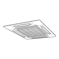
Indoor Unit External Views

Detailed external views and dimensions of various indoor unit types.

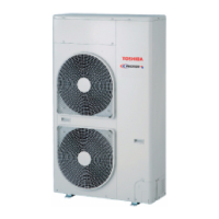
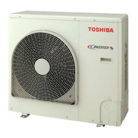
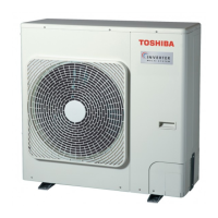
Outdoor Unit External Views

Detailed external views and dimensions of outdoor units.

Systematic Refrigerating Cycle Diagram

Indoor Unit and Outdoor Unit Cycle

Refrigerating cycle diagram illustrating components and operating conditions for indoor/outdoor units.

Wiring Diagram

Indoor Unit Wiring Diagram

Electrical wiring diagrams specific to indoor units, showing component connections.

Outdoor Unit Wiring Diagram

Electrical wiring diagrams for outdoor units, detailing component connections.

Specifications of Electrical Parts

Indoor Unit Electrical Parts

Specifications for electrical components used in indoor units.

Outdoor Unit Electrical Parts

Specifications for electrical components used in outdoor units.

Accessory Separate Soldparts

Specifications for optional accessory parts like drain kits and ceiling panels.

Refrigerant R410A

Safety During Installation and Servicing

Crucial safety precautions for handling R410A refrigerant during installation and servicing.

Refrigerant Piping Installation

Guidelines and material specifications for R410A refrigerant piping installation.

Tools for Refrigerant Handling

List and specifications of required tools for working with R410A refrigerant.

Recharging of Refrigerant

Step-by-step procedures for recharging the specified amount of R410A refrigerant.

Brazing of Pipes

Materials and techniques for brazing refrigerant pipes, including flux usage.

Control Block Diagram

Indoor Control Circuit Diagram

Block diagram illustrating the control circuit of the indoor unit.

Control Specifications

Detailed specifications for unit operation control logic and modes.

Indoor Print Circuit Board Layout

Layout and component identification for the indoor unit's main P.C. board.

Circuit Configuration and Control Specifications

Indoor Control Circuit Configuration

Overview of main control circuits within the indoor unit.

Outdoor Unit Controls

Specifications and functions related to the control systems of outdoor units.

Troubleshooting

Troubleshooting Summary

General troubleshooting steps, required tools, and confirmation points before diagnosis.

Check Code List

A comprehensive list of error codes, their causes, and diagnostic measures.

Outdoor P.C. Board LED Error Modes

Interpreting LED indications on the outdoor P.C. board for error detection.

Troubleshooting Procedures by Check Code

Detailed flowcharts for diagnosing and resolving specific check codes.

Replacement of Service Indoor P.C. Board

Setup at Local Site and Others

Indoor Unit Test Run Setup

Procedures for performing test runs on indoor units using remote controllers.

Local Site and Other Setup Procedures

Setup procedures for local sites, including TCC-LINK adapter and central control.

Central Control Address Setup

Instructions on how to set up central control address numbers for units.

Address Setup

Address Setup Procedure

Steps for setting up line, indoor, and group addresses for unit communication.

Address Setup and Group Control

Terminology and system configurations for address setup and group control.

Manual Address Setup

Procedure for manually setting addresses via the remote controller.

Detachments

Indoor Unit Detachments

Procedures for disassembling and removing various parts of the indoor unit.

Outdoor Unit Detachments

Procedures for disassembling and removing various parts of the outdoor unit.

Exploded Views and Parts List

Indoor Unit Exploded Views and Parts

Exploded diagrams and part numbers for indoor unit components.

Outdoor Unit Exploded Views and Parts

Exploded diagrams and part numbers for outdoor unit components.

Replacement of Main Parts (Sold Separately)

Procedures for replacing main parts like drain kits.

Cord Heater Installation Work

Related product manuals