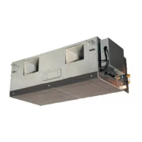
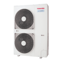
Do you have a question about the Toshiba RAV-SM1401AT-E and is the answer not in the manual?
Crucial safety precautions for R410A refrigerant handling during installation and servicing.
Specifies copper pipes and joints suitable for R410A, including material and thickness requirements.
Lists essential tools required for R410A installation, servicing, and general tools.
Step-by-step guide for recovering and recharging refrigerant into the air conditioning system.
Details materials for brazing, flux types, and brazing methods to prevent oxidation.
Explains the control specifications and components related to the outdoor unit.
Describes the core operational controls including PMV, temperature, current, fan, heating, and defrost functions.
Provides an overview of troubleshooting procedures, tools, and initial checks for common issues.
A comprehensive list of error codes detected by indoor and outdoor units, including causes and corrective measures.
Guides on interpreting outdoor unit LED status for diagnosing operational errors and faults.
Maps specific check codes and LED displays to their corresponding error causes and conditions.
Detailed diagnostic flowcharts and steps for resolving specific error codes and system malfunctions.
Outlines common procedures for safely detaching various components of the unit.
Details the steps for reattaching components correctly during assembly or repair.
| Brand | Toshiba |
|---|---|
| Model | RAV-SM1401AT-E |
| Category | Air Conditioner |
| Language | English |


 Loading...