Do you have a question about the Toshiba RAV-SM304MUT-E and is the answer not in the manual?
| Brand | Toshiba |
|---|---|
| Model | RAV-SM304MUT-E |
| Category | Air Conditioner |
| Language | English |
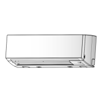
Wiring diagram for the compact 4-way cassette indoor unit.
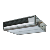
Wiring diagram for the concealed duct indoor unit.
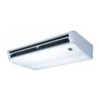
Wiring diagram for the ceiling type indoor unit.
List of electrical parts and their specifications for cassette type units.
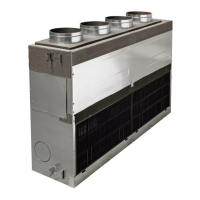
List of electrical parts and their specifications for duct type units.
List of electrical parts and their specifications for ceiling type units.
Block diagram showing indoor controller functions and connections.
Diagram for connecting both wired and wireless remote controllers.
Heating temperature correction and automatic capacity control (GA).
Logic for switching between cooling and heating operations.
Control logic for preventing cool air discharge in heating operation.
Control logic for freeze prevention based on sensor readings.
Procedure for setting up test run mode using wired remote controller.
General overview and procedure for troubleshooting air conditioners.
Summary of troubleshooting for wireless remote controller types.
Table correlating lamp indications to error codes and causes.
List of error codes related to sensors, EEPROM, and compressor systems.
List of indoor unit check codes, their causes, and troubleshooting measures.
Detailed table of indoor unit error modes, causes, and judgments.
List of error codes detected by the outdoor unit and their causes.
Detailed table of outdoor unit error modes, causes, and judgments.
List of error codes related to communication between controllers and units.
Flowcharts for diagnosing E01 and E09 communication errors.
Flowcharts for diagnosing E04 and E10 errors related to wiring and power.
Flowcharts for communication and group control errors.
Flowcharts for diagnosing controller and central system errors.
Flowcharts for diagnosing P10 (drain) and F10 (TA sensor) errors.
Flowchart for diagnosing P12 error related to the indoor fan motor.
Flowchart for diagnosing P19 error related to the 4-way valve.
Flowcharts for diagnosing F01 (TCJ sensor) and F02 (TC sensor) errors.
Flowchart for diagnosing C06 error in 1:1 model connection interface.
Diagnosis for E03 error when master unit cannot receive signals.
Diagnosis for F29 error indicating an EEPROM detection error.
Diagnosis for P31 error in follower units when master unit has errors.
Step-by-step guide for replacing the indoor unit P.C. board, including EEPROM handling.
Procedures for reading EEPROM data and setting jumper/connector configurations.
Detailed steps for writing setting data, including type and capacity, to the EEPROM.
Overview of the automatic address setup process upon power-ON.
Step-by-step guide to manually set addresses using the remote controller.