


J
John KennedyAug 2, 2025
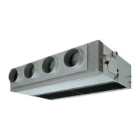
What to do if trouble occurred in Toshiba RAV-SM562CT-E Air Conditioner?
- NnkingAug 2, 2025
If you are experiencing issues with your Toshiba Air Conditioner, you should first check the troubleshooting procedure. If the problem persists, it is recommended to ask an authorized dealer or qualified service (maintenance) professional to repair or maintain the air conditioner.