Do you have a question about the Toshiba RAV-SM560XT-E and is the answer not in the manual?
Details specifications for indoor units.
Specifications for the 4-way air discharge cassette indoor unit.
Specifications for the concealed duct type indoor unit.
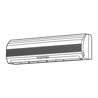
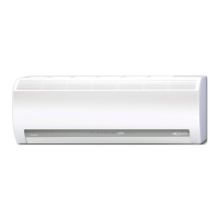
Specifications for the high-wall type indoor unit.
Specifications for the flexible type indoor unit.
Specifications for the outdoor unit.
Combined specifications of indoor and outdoor units.
Static pressure characteristics for different models of air ducting.
External construction views of the indoor unit.
External construction views for the concealed duct type indoor unit.
External construction views for the under ceiling/console type indoor unit.
External construction views of the outdoor unit.
Refrigerating cycle diagram for indoor and outdoor units.
Wiring diagram for the indoor unit.
Wiring diagram for concealed duct type indoor units.
Wiring diagram for high-wall type indoor units.
Wiring diagram for flexible type indoor units.
Wiring diagram for outdoor unit model RAV-SM800AT-E.
Electrical parts specifications for indoor units.
Electrical parts for concealed duct indoor units.
Electrical parts for high-wall indoor units.
Electrical parts specifications for outdoor units.
Specifications for separate accessory parts.
Safety precautions for handling R410A refrigerant during installation and servicing.
Guidelines for installing refrigerant piping with R410A.
Recommended piping materials and joint types for R410A systems.
Procedures for processing piping materials for R410A.
List of essential tools for R410A installation and servicing.
Procedures for recharging refrigerant in the system.
Recommended materials for brazing refrigerant pipes.
Procedures and precautions for brazing refrigerant pipes.
Block diagram of the indoor unit's control circuit.
Print circuit board details for concealed duct indoor units.
Block diagram of the microcomputer system.
Diagram for connecting wireless remote controllers to the system.
Detailed control specifications for system operation.
Print circuit board layout for indoor units.
Overview of the main control functions for indoor units.
Print circuit board layout for outdoor units.
Overview of the main control functions for outdoor units.
General troubleshooting steps and initial checks for common issues.
Troubleshooting specific to wireless remote controllers for cassette units.
List of error codes and their associated causes and solutions.
List of error modes detected by remote controllers or network adapters.
Troubleshooting procedures for specific error check codes.
Troubleshooting procedures for central control system check codes.
Setup procedures for indoor units at the installation site.
Steps for performing a test run setup using the remote controller.
Procedure for setting various functions via the remote controller.
Instructions for cabling and setting up remote controller control.
How to use the monitor function on the remote controller switch.
Functionality of the optional network adapter.
Functionality of the optional network adapter.
Block diagram of the network adapter's microcomputer.
Details on setting network addresses using the SW01 switch.
Specifications for the LED indicators on the network adapter.
Procedures for setting network addresses for indoor units.
Setting addresses and managing group control for indoor units.
Manual address setup using the remote controller.
How to confirm the position of indoor unit numbers.
Confirming indoor unit addresses within the group control.
General troubleshooting steps and initial checks for common issues.
Methods for judging the cause of errors based on unit displays.
Self-diagnosis procedures using check codes displayed on the remote controller.
Troubleshooting specific to wireless remote controllers.
Performing self-diagnosis using check codes.
Troubleshooting guide for remote controller check display.
Troubleshooting guide for RBC-AM1E remote controller check display.
Troubleshooting for central remote controller check display.
List of error codes and their associated causes and solutions.
Simple check methods for main indoor unit parts.
Simple check methods for main indoor unit parts.
Procedures for detaching main parts of the indoor unit.
Procedure for replacing the distributor assembly.
Procedures for replacing main parts in built-in type units.
Procedures for replacing main parts in hi-wall type units.
Step-by-step guide for replacing the main P.C. board.
Procedures for disassembling and attaching outdoor unit parts.
Exploded views and parts list for indoor units.
Exploded views and parts list for concealed duct indoor units.
Exploded views and parts list for high-wall indoor units.
Exploded views and parts list for specific high-wall models.
Exploded views and parts list for outdoor units.
Exploded views and parts list for outdoor unit model RAV-SM560AT-E.
Exploded views and parts list for outdoor unit model RAV-SM800AT-E.
Guide for installing cord heaters in applicable models.
Recommended parts required for cord heater installation.
Wiring diagram for cord heater installation.
Step-by-step procedure for installing cord heaters.
Final assembly steps after cord heater installation.
Technical drawing of the thermostat fixing plate.
| Cooling Capacity | 5.6 kW |
|---|---|
| Heating Capacity | 6.3 kW |
| Seasonal Energy Efficiency Ratio (SEER) | 6.1 |
| Power Supply | 220-240V, 50Hz |
| Refrigerant | R410A |
| Coefficient of Performance (Heating) | 3.61 |
| Outdoor Unit Dimensions (W x H x D) | 780 x 550 x 290 mm |
| Outdoor Unit Weight | 37 kg |
| Outdoor Unit Noise Level | 49 dB(A) |
| Power Source | 220-240V |
| Type | Split System Air Conditioner |