Do you have a question about the Toshiba RAV-SM560AT-E and is the answer not in the manual?
Detailed specifications for indoor units, covering various types like 4-Way Cassette, Concealed Duct, High-Wall, and Flexible.
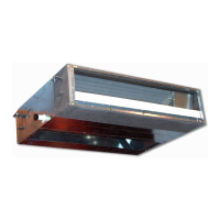
Specific technical data for the 4-Way Air Discharge Cassette type indoor unit.
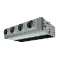
Technical specifications for the Concealed Duct type indoor unit.
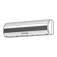
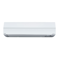
Technical specifications for the High-Wall type indoor unit.
Detailed specifications for the outdoor unit, including dimensions, power, and component details.
Wiring diagrams for indoor units, covering different types like 4-Way Cassette, Concealed Duct, High-Wall, and Flexible.
Wiring diagrams for the outdoor unit.
Safety precautions and guidelines for handling R410A refrigerant during installation and servicing.
Guidelines for installing refrigerant piping, including materials, joints, and processing.
Details on approved copper pipes and joints for R410A refrigerant systems.
Procedures for processing piping materials to prevent contamination and ensure proper installation.
Detailed procedures and precautions for flaring pipe connections with R410A refrigerant.
Step-by-step procedure for recharging refrigerant into the system.
Block diagram illustrating the indoor unit's control circuit.
Details on room temperature control, automatic capacity control, and setup ranges.
Block diagram showing the microcomputer system configuration for remote and indoor/outdoor units.
Detailed control specifications including power reset, operation modes, and temperature settings.
Details on room temperature control, automatic capacity control, and setup ranges.
Overview of main control functions including PMV, discharge temperature, and current release.
Details on the Pulse Modulating Valve control for cooling and heating operations.
Overview of main outdoor control functions including fan and coil heating.
Control logic for the outdoor fan based on TO sensor and compressor operation.
Control logic for the outdoor fan based on TO sensor and compressor operation.
General guide to troubleshooting, including required tools and initial confirmation points.
List of error codes detected by indoor and outdoor units, and remote controllers.
List of error modes detected by the indoor unit.
List of error modes detected by the outdoor unit.
List of error modes detected by the remote controller or network adapter.
Detailed procedures for diagnosing and resolving errors based on check codes.
Troubleshooting steps for errors related to the central control system.
Troubleshooting steps for various indoor unit errors (e.g., E10, CF, E18, 97, E08, L03, L09).
Troubleshooting steps for various outdoor unit errors (e.g., P29, H03, F06, F04, F08).
Troubleshooting for communication errors (97, E03) and power-related issues (F29, P31).
General troubleshooting guide for wall-type units, including tools and initial checks.
Troubleshooting using the CHECK display on the remote controller.
Procedure for interpreting CHECK codes displayed on wired remote controllers.
Troubleshooting steps using the remote controller with timer functions.
Table listing check codes and their corresponding error modes for indoor and outdoor units.
List of error modes detected by the indoor unit.
List of error modes detected by the indoor unit.
List of error modes detected by the outdoor unit.
Exploded views and parts lists for various indoor unit types.
Exploded views and parts lists for the outdoor unit.
| Brand | Toshiba |
|---|---|
| Model | RAV-SM560AT-E |
| Category | Air Conditioner |
| Language | English |