EasyManua.ls Logo

Toshiba RAV-SM307MUT-E User Manual

Toshiba RAV-SM307MUT-E
103 pages
To Next Page IconTo Next Page
Page #1 background imageLoading...
Page #1 background image
R410A
FILE NO. A10-1616
SERVICE MANUAL
AIR-CONDITIONER (SPLIT TYPE)
INDOOR UNIT
PRINTED IN JAPAN, Mar., 2017 ToMo
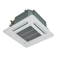
<Compact 4-way Cassette type>
RAV-SM307MUT-E (TR)
RAV-SM407MUT-E (TR)
RAV-SM457MUT-E (TR)
RAV-SM567MUT-E (TR)

Table of Contents

Questions and Answers:

Toshiba RAV-SM307MUT-E Specifications

General IconGeneral
BrandToshiba
ModelRAV-SM307MUT-E
CategoryAir Conditioner
LanguageEnglish

Summary

Qualified Installer and Service Person Definitions

Protective Gear and Safety Indicators

Protective Gear Requirements

Outlines necessary protective gear for various work tasks.

Safety Indication Explanations

Explains DANGER, WARNING, CAUTION symbols and prohibited/mandatory items.

Air Conditioner Unit Warning Labels

PRECAUTIONS FOR SAFETY

General Safety Precautions

Covers essential safety measures before, during, and after installation/maintenance.

Electrical Safety and Hazard Mitigation

Emphasizes circuit breaker use, avoiding live parts, and protective gear for electrical work.

Refrigerant Handling and Product Safety

Advises against modification, using specified parts, and safe refrigerant handling (R410A).

Declaration of Conformity

1. SPECIFICATIONS

Product Specifications Overview

Lists cooling/heating capacity, electrical characteristics, and dimensions for various models.

Specifications by Model Type

Provides ErP Lot-10 specifications for compact 4-way cassettes.

2. CONSTRUCTION VIEWS (EXTERNAL VIEWS)

3. WIRING DIAGRAMS

4. PARTS RATING

5. SYSTEMATIC REFRIGERATING CYCLE DIAGRAM

Refrigerating Cycle Diagrams by System Type

Shows cycle diagrams for single, twin, triple, and double-twin indoor unit combinations.

6. INDOOR CONTROL CIRCUIT

Indoor Control Circuit Block Diagrams

Shows block diagrams for wired and wireless remote controller connections.

Remote Controller Connection Types

Details connections for wireless remote controllers and optional kits.

6-2. Control Specifications

Indoor Unit Control Functions

Explains operation mode selection, temperature control, and automatic capacity control.

Air Speed and Special Operation Modes

Details air speed selection based on temperature and special operation controls.

Advanced Control Features Overview

Explains high-temp release, drain pump, after-heat elimination, and louver controls.

6-3. Indoor Print Circuit Board

Indoor Unit P.C. Board Layout and Connectors

Shows the layout and connectors of the indoor unit's main P.C. board.

Optional Connector Specifications

Details specifications for optional connectors like ventilation and occupancy sensors.

7. TROUBLESHOOTING

Troubleshooting Overview and Procedures

Provides a summary of troubleshooting steps, required tools, and general checks.

Troubleshooting by Check Code and Indications

Lists check codes for indoor unit troubles, their causes, and lamp indications.

Diagnostic Procedures for Specific Check Codes

Step-by-step diagnostic flows for specific error codes like E01, E09, E04.

Specific Component Troubleshooting

Troubleshooting for P12 (Fan motor) and F10 (TA sensor) issues.

8. REPLACEMENT OF SERVICE P.C. BOARD

Service P.C. Board Replacement Guide

Guides on replacing the indoor unit's service P.C. board, including data backup.

EEPROM Data Handling and Writing

Details reading and writing EEPROM data and board replacement steps.

9. SETUP AT LOCAL SITE AND OTHERS

Test Run Setup Procedures

Instructions for performing test runs using wired and wireless remote controllers.

Function Selection and Controller Operations

Procedures for forced defrost, LED indicators, function selection, and controller settings.

Remote Controller Monitor and Troubleshooting History

How to use the monitor function and recall past trouble history.

9-2. Setup at Local Site / Others

1:1 Model Connection Interface and Wiring

Details the function, wiring, and setup for the 1:1 model connection interface.

Central Control Address Setup

Guides on setting up central control address numbers via remote or unit side.

10. ADDRESS SETUP

Address Setup Overview and Procedures

Explains automatic and manual address setup for indoor/outdoor units and group control.

System Configurations and Group Control

Describes system configurations (single, twin, triple) and group control terminology.

Manual Address Setting from Remote Controller

Step-by-step guide for manual address setting using the remote controller.

Maintenance and Check List

11. DETACHMENTS

Component Detachment and Attachment Procedures

Procedures for removing and attaching major indoor unit components like grilles and covers.

Internal Component Replacement Guide

Steps for replacing the control P.C. board, fan motor, drain pump, and sensors.

12. EXPLODED VIEWS AND PARTS LIST

Indoor Unit Exploded Views

Exploded diagrams of the indoor unit for various models.

Comprehensive Parts Lists

Parts lists with location numbers and part numbers for all unit types and components.

Related product manuals