
L
Linda PhamSep 15, 2025
What does group line in individual indoor unit mean for Toshiba RAV-SM407KRTP-E?
What does group line in individual indoor unit mean for Toshiba RAV-SM407KRTP-E?
| Brand | Toshiba |
|---|---|
| Model | RAV-SM407KRTP-E |
| Category | Air Conditioner |
| Language | English |
Defines qualifications and knowledge required for installers and service personnel.
Details protective gear recommended for various work tasks.
Explains various warning labels and their meanings on the unit.
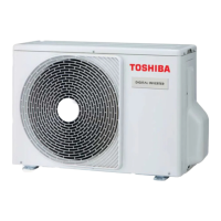
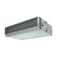
Provides detailed specifications for the High Wall type indoor units.
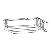
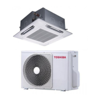
Illustrates external views and dimensions of the 4-way cassette type.
Shows clearance requirements for installation and servicing.
Diagrams the refrigerating cycle for High Wall type single systems.
Lists outer diameters of refrigerant pipes for indoor units.
Presents the wiring diagram for the High Wall type.
Lists specific electrical components and their types/specifications.
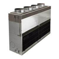
Identifies key parts of the indoor unit with descriptions.
Crucial safety precautions for handling R410A refrigerant.
Details requirements for installing refrigerant piping with R410A.
Specifies approved materials and joints for R410A piping.
Outlines procedures for cutting, deburring, and flaring pipes.
Lists required and general tools for R410A servicing.
Details tools specifically needed for R410A installation.
Step-by-step guide for recharging refrigerant.
Covers materials, flux, and methods for brazing refrigerant pipes.
Lists suitable brazing filler materials.
Explains the importance and types of flux used in brazing.
Describes brazing procedures, including oxidation prevention.
Shows the block diagram of the indoor control circuit.
Illustrates wiring for wired remote controller connections.
Illustrates wiring for wireless remote controller connections.
Details operational specifications and control logic for High Wall type.
Provides a layout of the indoor unit's print circuit board.
Provides an overview of troubleshooting steps and confirmation points.
Troubleshooting summary for wired remote controller systems.
Troubleshooting summary for wireless remote controller systems.
Detailed troubleshooting procedures for High Wall type.
Method for judging errors based on lamp indications and check codes.
Troubleshooting for issues not covered by specific check codes.
Lists indoor unit error check codes, causes, and solutions.
Step-by-step diagnostics for specific indoor unit error codes.
Notes on data backup and replacement procedures for the P.C. board.
Step-by-step instructions for replacing the service P.C. board.
Instructions for performing a test run using the remote controller.
Procedure to manually initiate a defrost cycle.
Explains the function of LEDs on the indoor unit's P.C. board.
Guide for setting various functions via the wired remote controller.
Details wiring and setup for single, dual, and group remote controller systems.
How to use the remote controller to monitor sensor data and operational status.
Procedure to retrieve and view past error logs.
Explains how to operate multiple indoor units as a group.
Overview of functions for TCC-LINK central control.
Illustrates the connection diagram for TCC-LINK central control.
Specifies wiring requirements for central control systems.
Details how to set onboard switches for central control.
Step-by-step guide to setting onboard switches.
Procedure for setting addresses for TCC-LINK central control.
Guide for manually setting refrigerant line addresses.
Guide for manually setting refrigerant line addresses for larger systems.
Explains the automatic and manual address setting process.
Defines terms and illustrates configurations for group/twin/triple control.
Detailed manual procedure for setting addresses via remote controller.
General safety warnings before performing disassembly or repairs.
Instructions for detaching and reassembling the front panel.
Procedure for removing and reinstalling electrical components.
Steps for removing and reinstalling the horizontal louver.
Guide for removing and reinstalling the evaporator/heat exchanger.
Instructions for removing and reinstalling the bearing.
Procedure for removing and reinstalling the fan motor.
Steps for removing and reinstalling the cross flow fan.
Important note regarding ordering service parts.
Diagram of parts with corresponding location and part numbers.
Safety guidelines specific to the Lite-Vision remote controller installation.
Lists the components included with the Lite-Vision remote controller.
Instructions for installing the Lite-Vision remote controller, including placement and wiring.
Identifies and explains the functions of remote controller buttons and display.
Guides through initial setup of clock, room name, and display settings.
Accessing advanced settings like test mode and service information.
Procedure for manually entering contact, model, and serial number data.
How to view and delete past alarm records from the remote controller.
Instructions for using the remote controller to monitor sensor data.
Procedure for performing advanced settings using DN codes.
Discusses limits for refrigerant concentration in rooms to prevent suffocation risks.