–12–
EN
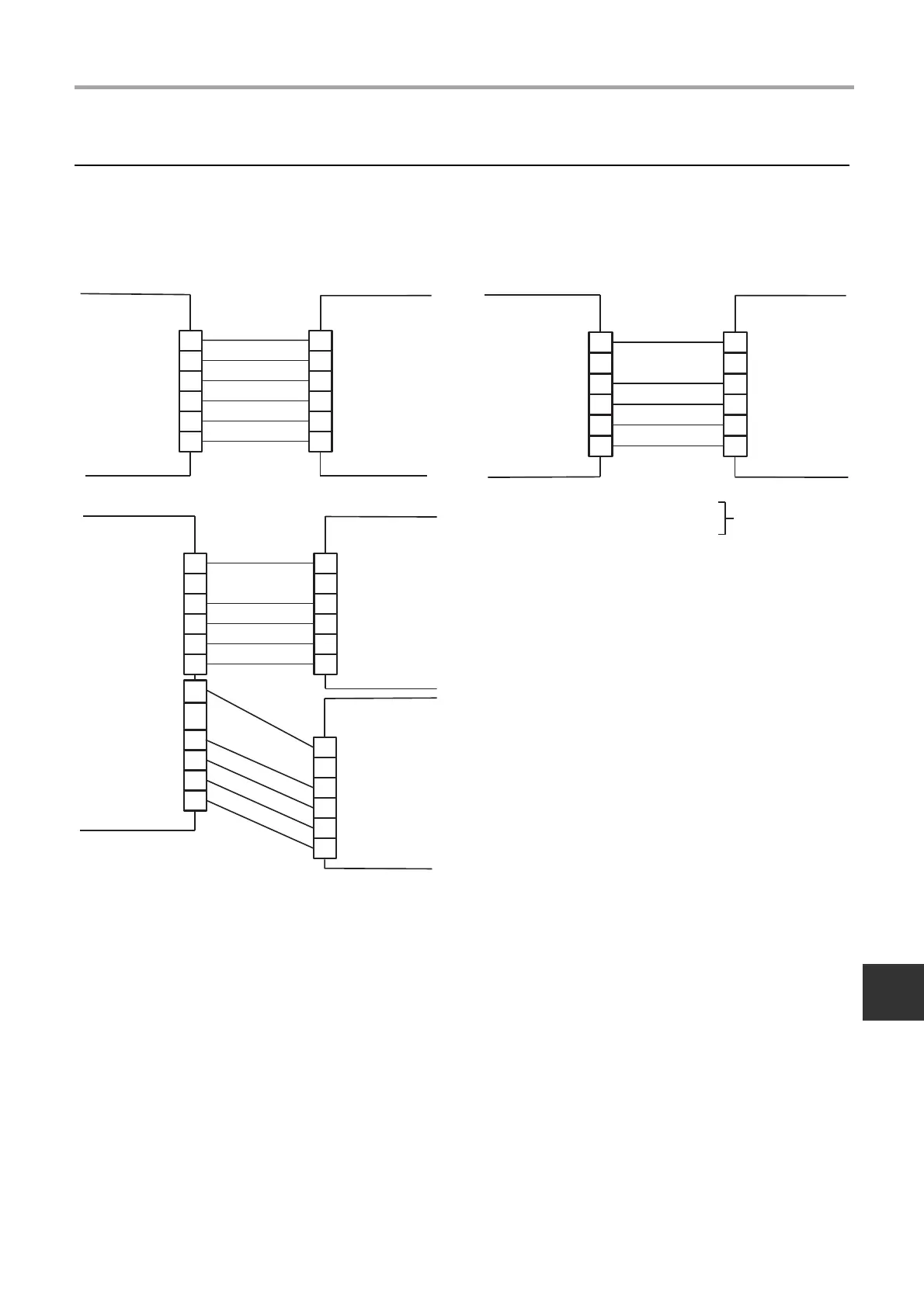
Electrical connection
The wiring from PMV is connected to Dx-coil controller.
Terminal R / BR / W / Y / OR / BL
• For the PMV, sensor wiring, do not bundle it with the motor wiring. The wrong operation may result in.
• The PMV cable cannot be extended, it is supplied at the maximum permissible length of 5 m.
Dx-Valve kit 1, Dx-Valve kit2 : Connect the cable from the PMV.
Match the color of the wiring of the PMV side and the controller side.
Dx-coil Valve kit
side
Dx-coil controller
side
Valve kit 1
8, 10 HP
Dx-coil Valve kit
side
Dx-coil controller
side
Valve kit 1
16, 18, 20 HP
48HP (16HP×3)
54HP (18HP×3)
60HP (20HP×3)
Only TA control type
Dx-coil Valve kit
side
Dx-coil controller
side
Valve kit 1
32, 36, 40 HP
Valve kit 2
Dx-coil Valve kit
side
12-EN
 Loading...


