–6–
EN
4. Installation
External dimensions and Installation space
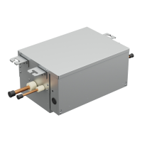
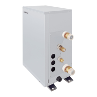
Be sure to install the controller, valve kit in the indoor. Failure to do so may cause the frost formation, rust, or malfunction.
(Unit: mm)
400
250
100
220
300 50
15
80
100
45
50
222
166
111
RBM-A101VAE
4-Ø 6.0 Mounting hole
Connection cable
(Factory wiring)
Terminal block (6p)
PMV motor
Connection cable
(Local wiring)
Refrigerant pipe connection port
(Liquid pipe / Outdoor unit side)
Refrigerant pipe connection port
(Liquid pipe / Air Handling unit side)
Note)
This product is designed for the indoor installation.
Upper side
300 or more
Floor
Ø 12.7
Ø 12.7
400
250
100
220
300 50
15
80
45
50
111
166
222
100
4-Ø 6.0 Mounting hole
Connection cable
(Factory wiring)
Terminal block (6p)
PMV motor
Connection cable
(Local wiring)
Refrigerant pipe connection port
(Liquid pipe / Outdoor unit side)
Refrigerant pipe connection port
(Liquid pipe / Air Handling unit side)
Note)
This product is designed for the indoor installation.
Upper side
300 or more
Floor
Ø 15.88
Ø 15.88
RBM-A201VAE
6-EN

 Loading...
