–8–
EN
TC1, TC2 and TCJ sensor position on DX COIL
Piping size and Y-joint
• Maximum real piping length between valve kit and Dx coil is up to 10 m.
Gas pipe
AHU
Capillary Tube
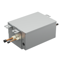
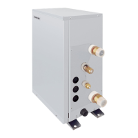
Dx-valve kit
PMV: Pulse
Motor Valve
Strainer
Brazing
Liquid pipe
TC2 Ø6 mm
(Brazing)
Air
Header
TC1 Ø4 mm
(Brazing)
TCJ Ø6 mm
(Brazing)
Max
10 m
Distributor
Dx-valve kit: 1 set (from 8HP to 20HP) DX COIL Type: Normal
DX COIL
Heat insulator
Capacity
Pipe diameter
(1) Gas pipe
(2) Liquid pipe (3) Liquid pipe
HP Ø
8 19.1 or 22.2
12.7
―
10 22.2 12.7
16 ~ 20 28.6 15.9
32 34.9 15.9 19.1
36 ~ 48 41.3 38.1*¹ 15.9 22.2
54 ~ 60 41.3 15.9 22.2
*1 Only SMMS-u
DX COIL
type
Normal
(Unit: mm)
HP Y-joint (A)
32
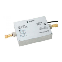
RBM-BY305E
Ø19.1-Ø15.9
36, 40
DX COIL
type
Normal
HP Y-joint (B)
32
RBM-BY305E
Ø15.9-Ø19.1
36, 40
DX COIL type Interlaced, Split face
HP Y-joint (C) Y-joint (D)
16, 18
RBM-Y205E
Ø15.9-Ø12.7
RBM-BY205E
Ø19.1-Ø28.6
20
RBM-BY205E
Ø22.2-Ø28.6
32
RBM-Y305E
Ø19.1-Ø15.9
RBM-BY305E
Ø28.6-Ø34.9
36, 40
RBM-Y305E
Ø22.2-Ø15.9
RBM-BY305E
Ø28.6-Ø41.3
DX COIL type Interlaced, Split face
HP Y-joint (E) Y-joint (F) Y-joint (G) Y-joint (H)
48
RBM-BY305E
Ø22.2-Ø15.9
RBM-BY305E
Ø15.9-Ø15.9
RBM-BY305E
Ø28.6-Ø34.9
RBM-BY305E
Ø28.6-Ø41.3
Ø34.9-Ø41.3
54, 60
RBM-BY305E
Ø28.6-Ø41.3
RBM-BY305E
Ø28.6-Ø41.3
Ø41.3-Ø41.3
8-EN

 Loading...
