TC Series (TCmini/TC200) Driver
GP-Pro EX Device/PLC Connection Manual
53
4G)
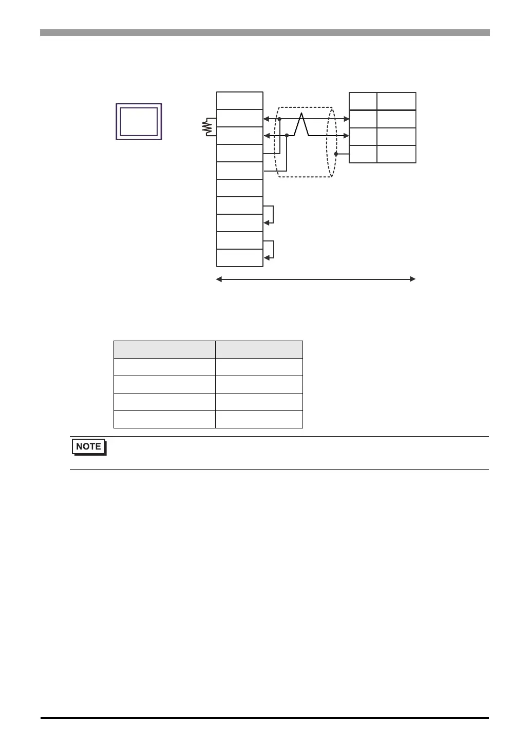
*1 The resistance built into the Display is used as termination resistance. Please set the DIP Switch in the back
of the Display as follows.
DIP Switch Setup Description
1OFF
2OFF
3ON
4ON
• To insert termination resistance of 120Ω on the External Device, turn on DIP Switch SW2-7.
• For the External Device connector, use the XH connector (XHP-6) by J.S.T. Mfg.
Signal name
Signal name
Pin
1
2
6
RDA
RDB
SDA
SDB
SG
ERA
CSA
ERB
CSB
A
B
FG
User-created cable
Display side
Terminal block
Display
External Device side
Terminal
resistance
*1
Shield
 Loading...


