10
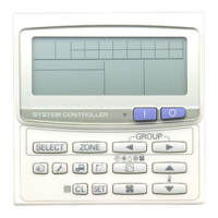
4. Address switch setting
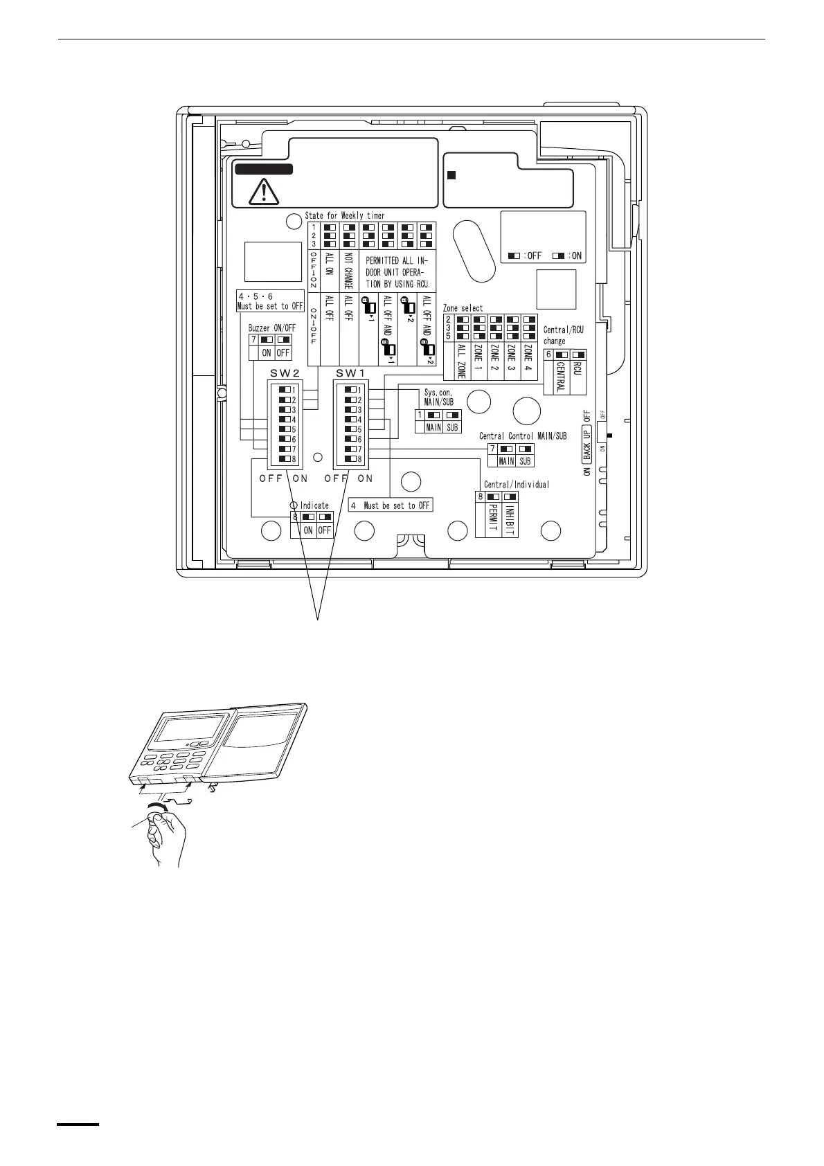
How to reach the P.C. board
Remove the flat-top screw on the bottom of the back case. When you
open up the decorative cover, you will see two notches under the
control unit. Inset a coin or other flat object into these notches and
pry off the back case. The P.C. board on the back of the control unit is
now visible.
WARNING
To avoid an electric shock hazard,
DO NOT touch any terminal on the
Printed Circuit Board with a metal
rod, a screwdriver edge nor a bare
hand when power is supplied.
After installation and adjust-
ment, be sure to turn the
BACK UP switch ON.
All bits are set off
when shipped from
factory.
To Installers,
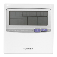
PCB of the control unit
Fig. 8
Dip switch
Fig. 9
Gap
Gap
Coin
OI-607-10EG
01_TCB-SC642TLE_EG_II.fm Page 10 Friday, June 25, 2004 3:04 PM
 Loading...