9
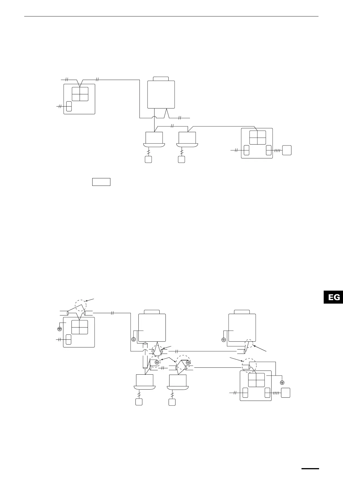
<Wiring connection procedure>
As shown in the figure below, connect the terminal block (U1/U3, U2/U4) of the
central controller with the terminals (U3, U4) of the outdoor unit (central unit).
• It is also possible to connect to the indoor/outdoor unit connecting wire
terminals (U1, U2) of the indoor or outdoor unit (no matter which refrigerant
system is used).
• Since the terminals do not have polarities, U1/U2 or U3/U4 can be reversed.
<Grounding the shielded wires>
• Terminate the connection of the shielded wires for all the central control
wires, and provide single-point grounding.
• Even when connecting the centrally controlled unit to the indoor/outdoor unit
connecting wires, terminate the connection of the shielded wires, and
provide single-point grounding for all the indoor/outdoor unit connecting
wires.
• Leave the final termination open (insulate it).
The fuse will blow to protect the equipment if an AC voltage of 220–240V is
applied by mistake to U1/U3 or U2/U4. If this should happen, first re-connect
the terminals properly, and then connect the communication wire to the U1/U3
and spare terminals. Check the fuse on the indoor/outdoor control board
since this fuse may have blown as well.
U1
U3
U2
U4
U1
U3
U2
U4
U1 U2
U1 U2
U1 U2 U3 U4
Power supply
Central control
system wire
Outdoor unit
(central unit)
Central controller
When connecting to MM{
indoor units (when connecting
to the indoor/outdoor unit
connecting wire)
Indoor/outdoor unit
connecting wire
Indoor unit
Power supply
Central controller
When connecting to MMY outdoor
units (when connecting to the
central control system wire)
Fig. 6
NOTE
U1
U3
U2
U4
U1
U3 U4
U3
U2
U4
U1 U2
U1 U2
U1 U2 U3 U4
A
C
A
B
B
Central control system wire
Power supply
Indoor/outdoor
unit connecting
wire shield
(single-point
grounding)
Indoor/outdoor
unit connecting
wire
Outdoor unit (central unit)
Indoor unit
Power supply
Central control
system wire shield
(single-point
grounding)
64-system central controller
When connecting to multiple indoor
units (when connecting to the
indoor/outdoor unit connecting wire)
64-system central controller
When connecting to multiple
outdoor units (when
connecting to the central
control system wire)
Fig. 7
Area A: Ground both ends of the shielded cable used for the indoor/outdoor
unit connection.
Area B: Connect a shielded cable for the central control system wiring.
Area C: Ground only one end of the central control system wiring at its final
termination. (Leave the other end of the wire at its final termination as an
open wire (i.e. insulate it).)
OI-607-09EG
01_TCB-SC642TLE_EG_II.fm Page 9 Friday, June 25, 2004 3:04 PM
 Loading...