8
How to wiring
How to wire the central controller
In order to ensure safety, turn off the air conditioner power before mounting or
removing the central controller.
• Connect the communication wires to the indoor/outdoor unit connecting
wires or central control system wires.
• Use the following as the communication wires.
Total wire length of less than 1,000 meters: MVVS1.25mm
2
Total wire length of less than 2,000 meters: MVVS2.0mm
2
The total wire length is obtained by adding the lengths of the indoor/outdoor
unit connecting wires to the lengths of the central control system wires.
• Do not run the communication wires inside the same electrical wire conduits
as the power cables, connect them using similar wires or allow them to be
routed near other wires.
• For the communication wires, use signal wires that visually identify them as
being different from either the remote controller wires or the power cables.
• Connect the power cable of the central controller to the AC220–240V power
source. (Incorrect wiring will damage the equipment.)
• Connect the wires in such a way that none of the wires will be connected
incorrectly. (Incorrect wiring will damage the equipment.)
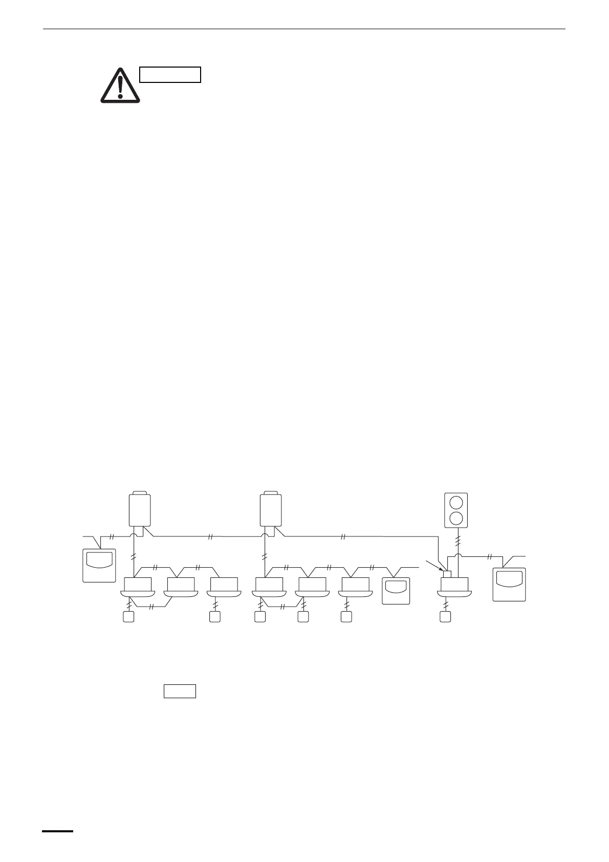
<Basic wiring diagram>
Connect the communication wires of the air conditioners shown which is the
wiring employed when using central control is used.
• The maximum number of air conditioners which can be connected in one
central control system is 64 indoor units and 16 outdoor units (center units).
(With Super Modular Multi system)
• Up to ten central controllers including other central control units can be
connected.
Ensure that wiring connections are correct. (Incorrect wiring will
damage the equipment.)
• When connecting to MMY outdoor units, make the connection to the
central control system wires (U3 and U4 terminals).
• When connecting to MM{ indoor units, make the connection to the indoor/
outdoor unit connecting wire (U1 and U2 terminals).
• When connecting to a RAV air conditioner, make the connection to the U3
and U4 terminals of the TCC-LINK.
• The TCC-LINK adapter is required for the RAV air conditioner. (except
KRT series.)
• A general-purpose unit control interface is required with some air
conditioner models.
CAUTION
1-1 1-2 1-3 2-1 2-2 2-3 3-1
Refrigerant
system 1
(MMY)
Refrigerant
system 2
(MMY)
Refrigerant
system 3 (RAV)
Central control system wire
When
connecting to
MMY outdoor
units
Indoor/outdoor unit
connecting wire
TCC-LINK
adapter
When connecting to
MM{ indoor units
When connecting a central
controller for RAV series
indoor unit (except KRT),
add the TCC-LINK adapter
on indoor unit.
Fig. 5
MM{: Super Modular Multi Indoor Unit model name.
(MMU, MMD, MMC, MML, MMK and MMF)
Central
controller
Central
controller
NOTE
OI-607-08EG
01_TCB-SC642TLE_EG_II.fm Page 8 Friday, June 25, 2004 3:04 PM
 Loading...