7
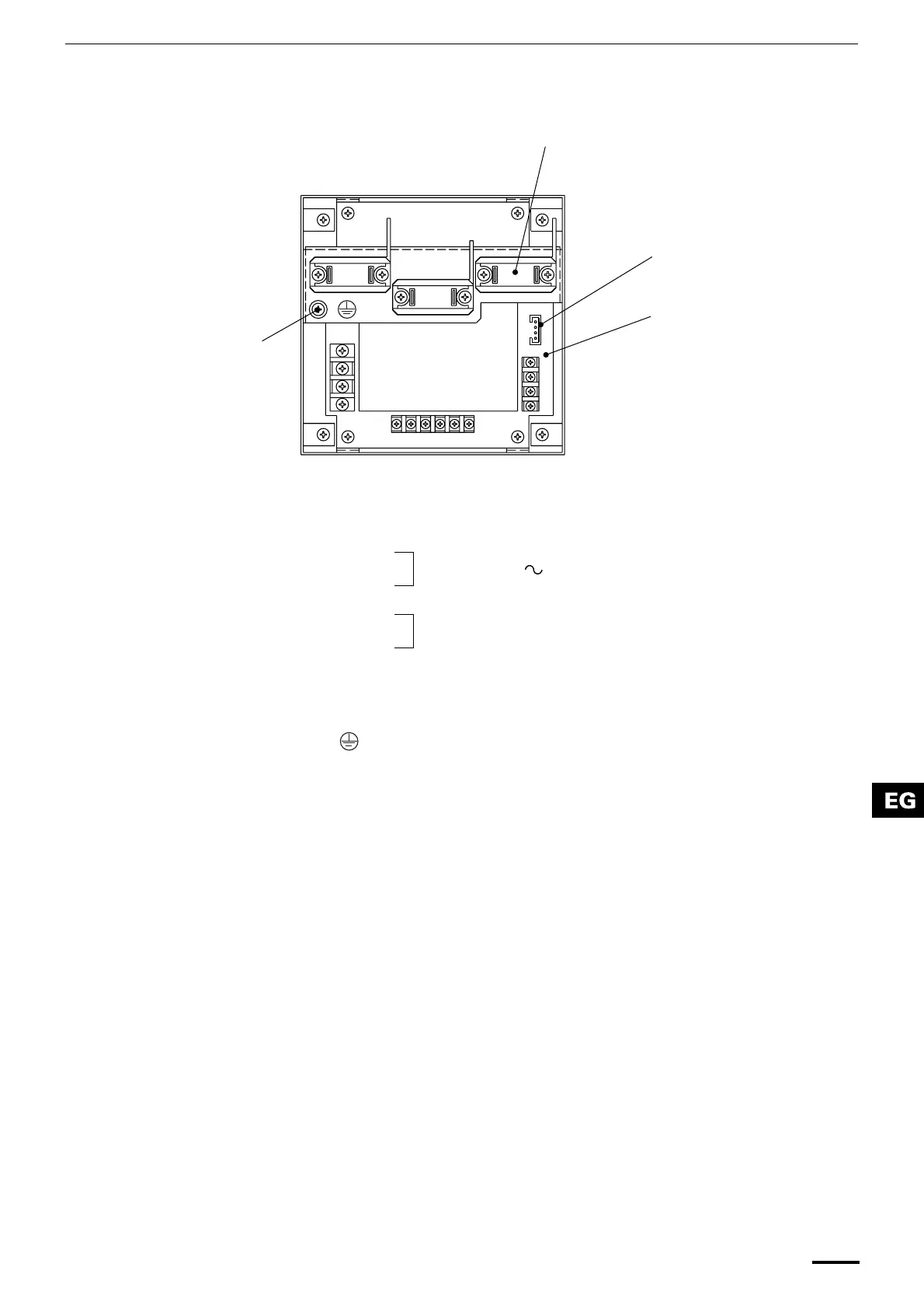
Layout of electrical terminals
How to connect electrical wiring
1) Basic wiring
2) Terminals for remote monitoring
L:
Power supply ( 50 Hz/60 Hz, 220–240 V)
N:
U1/U3:
Indoor unit control wiring. (Low voltage)
U2/U4:
C3: Auxiliary
C4: Ground for inter-unit control wiring
: Ground for power wiring
A1: Input for turning on air conditioners concurrently.
A2: Input for turning off air conditioners concurrently.
A3: Common input for turning air conditioners on or off.
B1: On operation state indicator output.
B2: Alarm indicator output.
B3: Common indicator output.
N
L
B3 B2 B1 A3 A2 A1
U1/U3
U2/U4
C3
C4
CN02
Clamp for electrical wiring
Connector (CN02) for
weekly timer or schedule
timer (optional)
P.C. board
Ground for
power wiring
Fig. 4
OI-607-07EG
01_TCB-SC642TLE_EG_II.fm Page 7 Wednesday, June 30, 2004 4:54 PM
 Loading...