43
This makes the inverter ideal for your electronic applications such as
washing machines treadmill, showcase refrigerators for stores, medical
equipment, and stage equipment where attention must be paid to
peripheral devices.
*1:Photos of machinery are for illustrative purposes only.
This makes the inverter ideal for drilling machines, handling machines,
conveyors, semiconductor production equipment, cutting machines, and
woodworking machinery that require simple function.
*1:Photos of machinery are for illustrative purposes only.
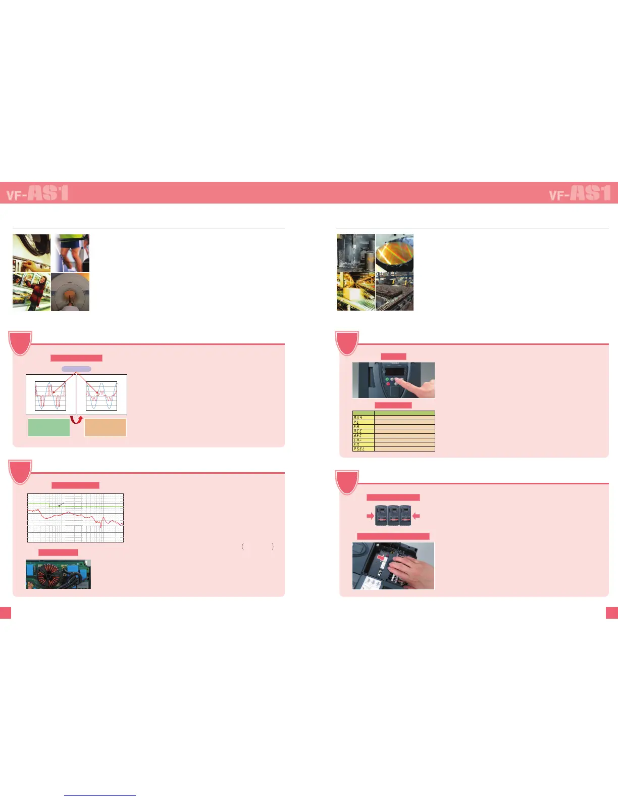
Input current
Conventional models (400 V, 30 kW)
Input current value 87.6 A
Overall input power factor 59%
VF-AS1 (400 V, 30 kW)
Input current value 58.8 A
Overall input power factor 88%
Title Function
Parameter setting macro function
V/f control mode selection
Maximum frequency
Acceleration time 1
Deceleration time 1
Motor overload protection level 1
FM terminal meter adjustment
Parameter display selection
For your commercial facilities, offices and factories
•A compact, space-saving new type of DC reactor is built
into 200 V class 11 to 45 kW and 400 V 18.5 to 75 kW
models.
In addition to reducing harmonics, this reactor limits the
input current to 110% of the rated output current, and it has
been designed to be compatible with power supply systems
containing transformers, molded-case circuit breakers, and
power lines.
Adding on the optional DC reactor enables compliance with
IEC harmonics standards.
Harmonics Reduction, Power Factor Improvement
• High-frequency noise is drastically reduced on models with
built-in noise filters. Built-in noise filters are ideal for sites
from commercial facilities and offices through to factories
where attention must be paid to peripheral devices.
Compared with filter not integrated models, space and
wiring savings have been achieved by incorporating the
filter in the panel. Also, models with built-in EMC noise
filter comply with the European EMC Directive as
individual inverter units.
High-frequency Noise Reduction
200V class models, 0.4 to 7.5kW : EMI noise filter (complies with the European EMC Directive) built-in standard
200V class models, 11 to 45kW : Basic noise filter (not complies with the European EMC Directive) built-in standard
400V class models, 0.75 to 75kW : EMI noise filter (complies with the European EMC Directive) built-in standard
400V class models, 90 to 500kW : EMI noise filter (complies with the European EMC Directive) built-in standard
European EMC Directive : IEC/EN61800-3, 1st Environment, C2
or
IEC/EN61800-3, 2nd Environment, C3
For machinery that requires simple function
POINT
• In the Quick mode, pressing the EASY key on the panel allows
you to operate the inverter by eight basic parameters.
When setting each of the functions, press the EASY key to move
to the standard mode by one-touch operation. In this mode, you
can access all parameters.
• You can customize the Quick mode display, maximum of 32
target parameters are displayed to suit your specific setup
requirements.
• You can also use the EASY key as a panel/remote key to switch
between panel and remote operation, and as a shortcut key to
directly access any specific setup or display screen.
Simple Setup by EASY Key
Side-by-side installation
• Side-by-side installation of inverters is possible up to the inverter’s
total capacity. This allows effective utilization of space inside
control panels. Heat sink can be installed outside of the panel as
an option.
Removable control terminal board
•A removable terminal board is used. This allows you to use the
control wiring when replacing the inverter, which also makes
maintenance easier.
ON/OFF control of cooling fan
• Temperature-based ON/OFF control reduces noise while the inverter
is being stopped, saves energy and extends the cooling fan’s life.
Monitoring of serviceable parts/alarm output
• The expected replacement cycle of main circuit capacitors,
capacitors on control board, and cooling fan is monitored, and an
alarm is output when the cycle is reached.
Easy Installation, Easy commissioning, and Easy maintenance
0.15 1 10
30
100
80
60
40
20
Frequency [MHz]
[dBuV]
Side-by-side installation
Removable control terminal board
EN61800-3 1st Environment Category C2
1
Point
300
200
100
-100
-200
-300
0
600
400
200
-200
-400
-600
0
0 200 400 600
300
200
100
-100
-200
-300
0
600
400
200
-200
-400
-600
0
0200400600
Voltage [V]
2
Point
3
Point
4
Point
Current [A]
Voltage [V]
Example of generated noise data
Current [A]
Effect of built-in reactor
Input current/voltage waveform Input current/voltage waveform
Effect of built-in filter
Built-in EMC filter
200V-0.4 to 1.5kW
400V-0.75 to 3.7kW
Quick mode (EASY)
EASY key
 Loading...