*1: Main circuit power supply
3ph-240V class: three-phase 200-240V-50/60Hz
1ph-240V class: single-phase 200-240V-50/60Hz
1ph-120V class: single-phase 100-120V-50/60Hz
*2: The inverter is supplied with the PO and the PA/+ terminals shorted by means of a shorting bar.
Before installing the DC reactor (DCL), remove the bar.
*3: When using the OUT output terminal in sink logic mode, short the NO and CC terminals.
When using the NO output terminal in source logic mode,short the P24 and OUT terminals.
*4: 1ph-240V models have noise filter inside.
*5: 1ph-120V models cannot be used with DC reactors.
*6: When external potentiometer is connected by using P5 terminal, set the parameter f109=3
*7: When using VI terminal as a logic input terminal, set the
parameter f109=2 and connect as following
schematics. Be sure to connect a resistor between
P24 and VI terminals in case of sink logic, between
VI and CC terminals in case of source logic.
(Recommended resistance: 4.7k -1/2W)
The T/L3 terminal is not provided for
single-phase models.
Use the R/L1 and S/L2/N terminals as input terminals.
Single phase
power supply
< Sink logic > < Source logic >
Note 1. Be sure to attach a surge killer to the exciting coil of the relay and the magnetic contactor.
Note 2. When using the auxiliary contacts 2a of the magnetic contactor MC for the control circuit, connect the contacts 2a in parallel to increase reliability.
Note 3. When a motor is driven by commercial power supply using commercial power supply / inverter switching circuit, use a magnetic contactor appropriated AC-3 class the motor rated current.
Note 4. Select an MCCB with a rataed interrupting current appropriate to the capacity of the power supply, because short-circuit currents vary greatly depending on the capacity of the power supply
and the condition of the wiring system. The MCCB, MC and ELCB in this table were selected, on the assumption that a power supply with a normal capacity would be used.
Note 5. Sizes of the wires connected to the input terminals R/L1, S/L2 and T/L3 and the output terminals U/T1, V/T2 and W/T3 when the length of each wire does not exceed 30m.
The numeric values in parentheses refer to the sizes of wires to be used when a DC reactor is connected.
Note 6. For the control circuit, use shielded wires 0.75 mm2 or more in diameter.
Note 7. For grounding, use a cable with a size equal to or larger than the above.
Note 8. The wire sizes specified in the above table apply to HIV wires (cupper wires shielded with an insulator with a maximum allowable temperature of 75°C) used at an ambient temperature of 50°C or less.
Voltage
class
3-phase
240V
Inverter type
Molded -case circuit breaker (MCCB)
Earth leakage circuit breaker (ELCB) Note4)
Magnetic contactor (MC)
Note1) 2) 3)
Applicable
motor
(kW)
Rated current (A)Rated current (A)
Input current (A)
No reactor
With DC
reactor
No reactor
With DC
reactor
No reactor
With DC
reactor
Main circuit
Note5)
DC reactor
(optional)
Grounding
cable
Note7)
Wire size (mm
2
)
Note8)
0.1
0.2
0.4
0.75
1.5
2.2
4.0
0.1
0.2
0.4
0.75
1.5
2.2
0.1
0.2
0.4
0.75
VFNC3-2001P
VFNC3-2002P
VFNC3-2004P
VFNC3-2007P
VFNC3-2015P
VFNC3-2022P
VFNC3-2037P
VFNC3S-2001PL
VFNC3S-2002PL
VFNC3S-2004PL
VFNC3S-2007PL
VFNC3S-2015PL
VFNC3S-2022PL
VFNC3S-1001P
VFNC3S-1002P
VFNC3S-1004P
VFNC3S-1007P
1-phase
240V
1-phase
120V
1.2
2.0
3.6
6.3
11.1
14.9
23.8
2.0
3.4
5.9
10.2
17.8
24
3.5
6.0
11.4
18.9
0.6
0.9
1.8
3.5
6.6
9.3
16.1
1.2
2.1
4.1
7.7
14.8
20.3
−
−
−
−
5
5
5
10
15
20
30
5
5
10
15
30
30
5
10
15
30
20
20
20
20
20
20
32
20
20
20
20
20
32
20
20
20
20
20
20
20
20
20
20
20
20
20
20
20
20
32
−
−
−
−
1.5(1.5)
1.5(1.5)
1.5(1.5)
1.5(1.5)
1.5(1.5)
2.5(1.5)
4.0(2.5)
1.5(1.5)
1.5(1.5)
1.5(1.5)
1.5(1.5)
2.5(2.5)
4.0(4.0)
1.5
1.5
2.5
4.0
1.5
1.5
1.5
1.5
1.5
1.5
4.0
1.5
1.5
1.5
1.5
1.5
1.5
−
−
−
−
2.5
2.5
2.5
2.5
2.5
2.5
4.0
2.5
2.5
2.5
2.5
2.5
4.0
2.5
2.5
2.5
4.0
5
5
5
5
10
15
30
5
5
5
10
20
30
−
−
−
−
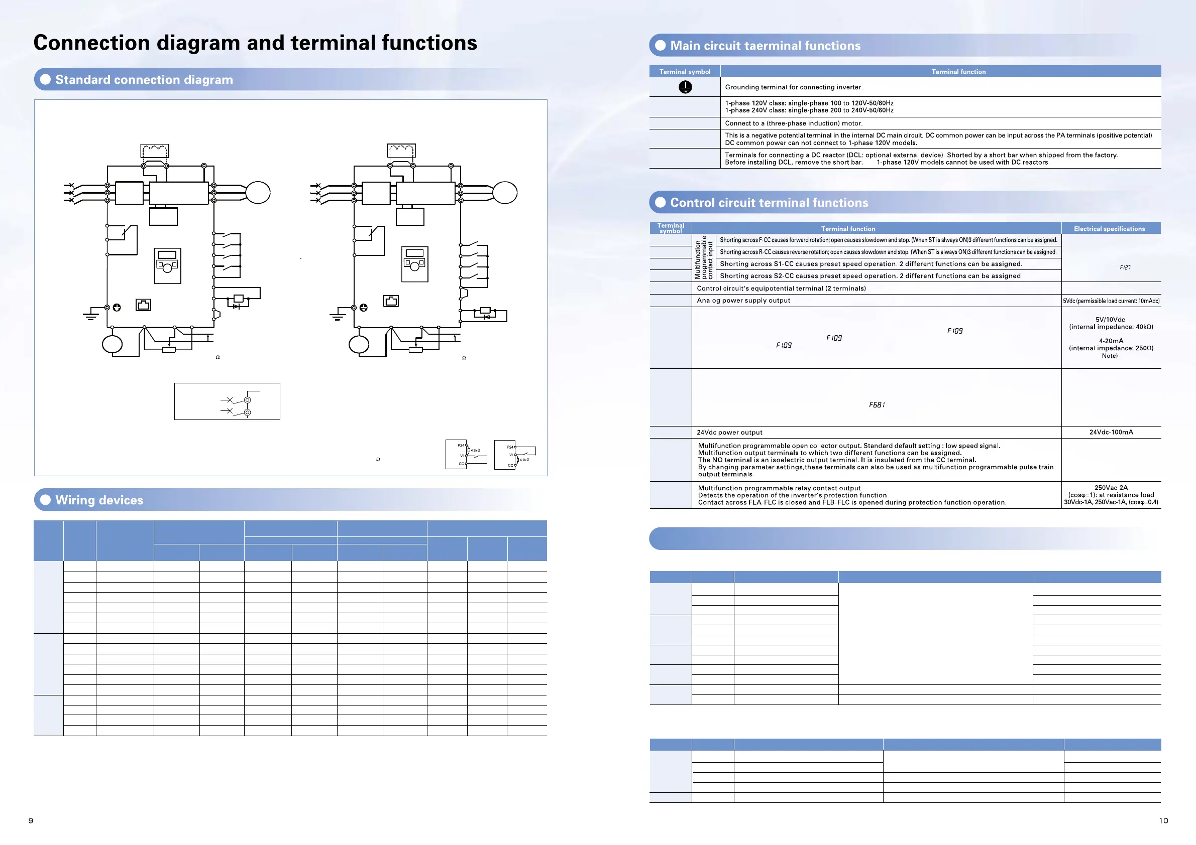
Multifunction programmable logic input/output
MCCB
*1
R/L1
S/L2
T/L3
U/T1
V/T2
W/T3
Motor
F
R
S1
S2
CC
P24
OUT
NO
CC
FM
CC VI
P5
+
+
-
-
P0
PA/+ PC/-
Meter
Voltage signal: 0-5V/0-10V
(Current signal: 4-20mA)
External potentiometer (1k-10k
)
Protective function
activation output
Ry
VF-nC3
Power
circuit
Noise
filter
DC reactor (DCL)
*2 , *5 (option)
Forward
Reverse
Preset-speed 1
Preset-speed 2
Common
7.5V-1mA
(or 0-10V/4-20mA)
Low-speed
signal output
*3
*4
Control
circuit
I M
Frequency
meter
(ammeter)
Operation panel
RS485
communication
connector
*7
*6
MCCB
*1
R/L1
S/L2
T/L3
U/T1
V/T2
W/T3
Motor
NO
CC
+
+
-
-
P0
Meter
External potentiometer (1k-10k
)
Control
circuit
Protective function
activation output
VF-nC3
Power
circuit
DC reactor (DCL)
7.5V-1mA
(or 0-10V/4-20mA)
FM
CC
VI
P5
PA/+
PC/-
Voltage signal: 0-5V/0-10V
(Current signal: 4-20mA)
Low-Speed
signal output
Ry
*4
Noise
filter
I M
Frequency
meter
(ammeter)
RS485
communication
connector
Operation panel
*2 , *5 (option)
*7
*6
F
R
S1
S2
OUT
Forward
Reverse
Preset-speed 1
Preset-speed 2
*3
P24
Common
Logic input terminal
3-pahse 240V class: three-phase 200 to 240V-50/60Hz
* Single-phase input: R/L1 and S/L2/N terminals
No voltage logic input
24Vdc-5mA or less
* Sink / Source selectable using
parameter
(Explanation in case of sink logic)
Multifunction programmable analog input.
Factory default setting: 0-10Vdc(10 bits resolution) and 0-60Hz (0-50Hz) frequency input.
The function can be changed to 4-20mAdc (0-20mA) current input by parameter =
1
setting and 0-5Vdc (10 bits
resolution) voltage input by parameter =
3
setting.
By changing parameter =
2
setting, this terminal can also be used as a multifunction programmable logic
input terminal. Be sure to insert a resistor between P24-VI (4.7 k
-1/2 W) in case of sink logic, between VI-CC in
case of source logic.
1mAdc full-scale ammeter
0-20mA (4-20mA) DC ammeter
Permissible load resistance:
750
Ω
or less
0-10V DC volt meter
Multifunction programmable analog output. Standard default setting: output frequency.
The function can be changed to 0-10Vdc voltage
or 0-20mAdc (4-20mA) current output by parameter setting.
Parameter Function Default settingAction
F
R
S1
S2
VI
Set the function number to each parameters.
In case of using one function, please set
.
In case of set two functions, OUT outputs by ‘AND’/’OR’ logic.
Select logic or pulse train output.
Set the function number.
2(Forward run)
0(No function)
0(No function)
4(Reverse run)
0(No function)
0(No function)
10(Preset-speed command 1)
0(No function)
12(Preset-speed command 2)
0(No function)
0(Voltage input signal 0 to 10V)
14(Preset-speed command 3)
Input terminal selection 1A
Input terminal selection 1B
Input terminal selection 1C
Input terminal selection 2A
Input terminal selection 2B
Input terminal selection 2C
Input terminal selection 3A
Input terminal selection 3B
Input terminal selection 4A
Input terminal selection 4B
Analog/ logic input selection (VI terminal)
Input terminal selection 5
Set
f1 0 9
=
2
(Logic input) for logic input.
Set the function number.
Set the function number to each parameters.
Two or more functions can be set to one terminal.
All functions operate by the signal input
OUT
FL(A, B, C)
4(Low speed detection)
255(Always ON)
0(AND)
0(Logic)
10(Failure signal (trip output))
Output terminal selection 1A
Output terminal selection 1B
Output terminal logic selection
Logic output/pulse train output selection
Output terminal selection 2
Logic output terminal
Terminal
symbol
Parameter Function Default settingAction
Terminal
symbol
Note) All of logic output terminals are turned off about 0.5 to 1 second when power-on and fault reset. Please pay attention to use negative logic outputs.
Note) When using the VI terminal as logic input terminal, be sure to connect a resistor between P24 and VI terminals in case of sink logic, between VI and CC terminals in case of source logic.
(Recommended resistance: 4.7k
-1/2W )
Note) If 4-20mA is selected, when the inverter’s power is ON, the intertnal impedance is 250
Ω, but when the power is OFF, the intertnal impedance increases very much to approximately 40kΩ.
Standard connection diagram-(sink logic)
(Negative)(common:CC)
Standard connection diagram-(source logic)
(Positive)(common:P24)
Open collector output 24Vdc-100mA
To output pulse trains, a current of
10mA or more needs to be passed.
Pulse frequency range: 38
1600pps
R/L1,S/L2,T/L3
U/T1,V/T2,W/T3
PC/-
PO, PA/+
F
R
CC
P5
VI
FM
P24
FLA
FLB
FLC
S1
S2
OUT
NO

 Loading...


