E6581172①
10
Contact input terminal function
(related with light-load high-speed operation)
4.2. Input/output terminal function
This section describes the functions as shown on the following table, which are not detailed in the instruction
manual of inverter unit among input/output terminal functions related with light-load high-speed operation.
Contact output terminal function
(related with light-load high-speed operation)
Parameter setting value Parameter setting value
Positive logic Negative logic
Function
Positive logic Negative logic
Function
106 107 Light-load output
120 121
Light-load high-speed
operation enabling signal
108 109 Heavy load output
4.2.1. Input terminal function (light-load high-speed operation
enabling signals 120 and 121)
This function is only effective during F330 (light-load high-speed operation selection)=4, 5, 9 or 10 (enabled-
terminal effective mode). It shall be used in case of setting light-load high-speed operation to enabled or disabled at
external terminals.
This function can be assigned to input terminals F, R, ST, RES, S1, S2, S3 and S4.
Refer to an example of assignment to S4 terminal in section 4.1.2 "Operation with F330=2, 4, 7 or 9 (automatic
mode)".
Using this function allows light-load high-speed operation from external input terminals. Therefore, it is
recommended to use this function when you want to control whether light-load high-speed operation is performed or
not using terminal ON/OFF signals.
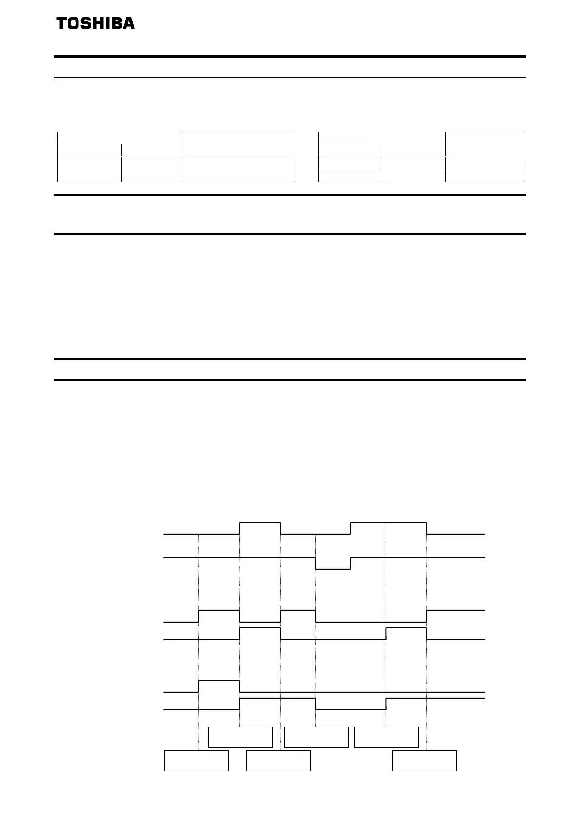
4.2.2. Output terminal function (load detection outputs 106~109)
This function provides two types of output patterns depending on F330 (light-load high-speed operation selection)
settings.
1) F330=0: In case of setting disabled light-load high-speed operation
The following figure indicates the timing chart of load detection signal.
After light-load detection time (F333) in disabled light-load high-speed operation mode, simple light-load or
heavy load output will be performed depending on load conditions.
2) F330≠0: In case of setting light-load high-speed operation
The following figure indicates the timing chart of load detection signal.
In light-load high-speed operation mode, even if light load is detected after heavy load detection, no light-load
detection output will be performed (under heavy load detection) until reset (shut-down command) as described
in section 4.1.
Operation signal ON OFF
In case of F330≠0
In case of F330=0
Light-load detection
signal
OFF ON
Heavy load detection
signal
Heavy load detection
signal
ON OFF
Light-load detection
signal
OFF ON
ON OFF
Load judgement Light load
Heavy load
Heavy load
detection
Reset
Heavy load
detection
Light-load
detection
Light-load
detection
Light-load
udgement
 Loading...