EasyManua.ls Logo

Toyota 00016-32901 - User Manual

Toyota 00016-32901
10 pages
Print Icon
To Next Page IconTo Next Page
Loading...
Item # Quantity Reqd Description
1 1 Keyless Module
2 1 Main Harness
3 1 Hardware Bag
4 1 Valet Switch
5 2 24" Cable Ties
6 2 3-Button Transmitter
7 1 Owner's Card
00016-79200-01 1
Keyless Entry Control Module
00016-34030-05 2 Keyless Entry Transmitter
00016-32901-01 1 Main Wiring Harness
00016-30960-56 1 On/Off Toggle Control Switch
00016-32901-02 1 Miscellaneous Hardware Kit
00016-30960-09 1 34" Headlight Extension Wire
Phillip screwdriver Straight-Slot screwdriver
Ratchet w/extension
10 mm socket
Diagonal wire cutters Common pliers
Flashlight Nylon trim tool
Torque Wrench 48" lbs
Item # Quantity Reqd Description
1 8 Red T-Taps
2 8 Black T-Taps
3
2 Blue T-Taps
4 6 8" Cable Ties
5 1 2-1/4"x 2-1/4" Foam Pad
6 1 Yellow T-Tap
NOTE: Not for installation on vehilce's equipped with
factory installed keyless entry.
Power door locks required
Kit Contents
Hardware Bag Contents
Conflicts
Recommended Tools
General Applicability
Safety Tools
Special Tools
I
NSTALLATION TOOLS
Special Chemicals
Vehicle Service Parts (may be required for reassembly)
Part Number: 00016-32901
Accessory Code: KE10
Legend
* Mandatory
STOP: Damage to the vehicle may occur. Do not
proceed until process has been complied with.
OPERATOR SAFETY: Use caution to avoid risk
of injury.
CRITICAL PROCESS: Proceed with caution to
ensure a quality installation. These points will be
audited on a completed vehicle installation.
TOOLS & EQUIPTMENT: This calls out the
specific tools and equipment required for this
process.
REVISION MARK: This mark highlights a change
in installation with respect to previous issue.
SAFETY TORQUE: This mark indicates that
torque is related to safety.
S
SPECIAL NOTE:
After TMS and Safety mandated preparatory steps have been
taken, the ins
tallation sequence is the suggested method for
completing the
accessory installation. In some instances the
suggested sequ
ence is written for one associate to install and
in others the
sequence is given as part of a team accessory
installation.
Unless otherwise stated in the document, the
associates may
perform the installation steps in any order to
make the inst
allation as efficient as possible while maintaining
consistent qua
lity.
Recommended Sequence of Events
Item # Accessory
Color Applicability/Trim Level
Vehicle/Trim Color
yrosseccA
roloC
TOYOTA Camry 2012 - Keyless Entry System
Southeast Toyota Distributors, LLC 1 of 10
Question and Answer IconNeed help?

Do you have a question about the Toyota 00016-32901 and is the answer not in the manual?

Summary

Conflicts and Applicability

Conflicts

Notes installation restrictions, especially for vehicles with factory keyless entry.

General Applicability

Specifies prerequisites for installation, such as power door locks.

Kit Contents and Tools

Kit Contents

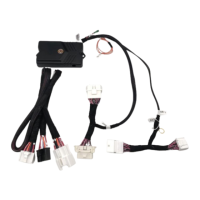
Lists all components included in the keyless entry system kit.

Hardware Bag Contents

Details the fasteners and small parts provided in the hardware bag.

Recommended Tools

Lists essential tools and safety equipment required for installation.

Installation Guidance

Recommended Sequence of Events

Outlines the suggested order for performing installation tasks.

Vehicle Service Parts

Identifies optional service parts that may be needed during reassembly.

Legend and Notes

Explains symbols, warnings, and special instructions for the installation process.

Installation Preparation

Familiarize and Inspect

Advise to review instructions and check kit components before starting.

Vehicle Preparation

Steps for preparing the vehicle, including protective coverings and battery disconnection.

Panel Removal

Drivers Side Kick Panel Removal

Instructions for carefully removing the driver's side kick panel.

Drivers Side Scuff Plate Removal

Guidance on removing the driver's side scuff plate.

Side Dash Panel Removal

Steps for removing the driver's side dash finish panel.

Preparing for Installation

Lower Finish Panel Removal

Details on removing the driver's side lower finish panel and hood release cable.

Lower Crash Shield Removal

Optional steps for removing the driver's lower crash shield and protecting the area.

Steering Wheel Shroud Removal

Instructions for removing the lower steering column cover.

Module Preparation

Antenna and Module Securing

Steps to attach the antenna to the module and route it with cable ties.

Mounting Main Control Module

Module Mounting Procedure

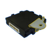
Guidance on securing the main control module to the dash brace using cable ties and adhesive.

Installation Procedures

Mounting the Toggle Switch

Steps for installing the ON/OFF toggle switch and securing its harness.

Securing Module Ground

Instructions for connecting the system's ground wire and torquing the bolt.

T-Tap Installation

Detailed guide on correctly installing female T-Tap connectors for wiring.

Wiring Diagram

Wiring Connections Overview

Visual guide detailing all electrical connections for the keyless entry system.

Connector Details

Connector 136: Ignition Switch

Details pin assignments for the ignition switch connector.

Connector 125: Tailights

Details pin assignments for the tailights combination switch connector.

Connector 128: Horn

Details pin assignments for the horn spiral spring connector.

Connector KI1: Door Locks

Details pin assignments for the driver's kick panel door lock connectors.

Completing the Installation

Testing the System

Procedures for testing all keyless entry features after installation.

Reassembling Panels

Instructions for reattaching all removed interior panels.

Preparing Vehicle for Delivery

Steps for setting chirps and placing the owner's card.

Programming Transmitters

Programming New or Replacement Transmitters

Step-by-step guide for programming remote transmitters to the security module.

Vehicle Function Checklist

Final System Function Verification

Comprehensive checklist to ensure all vehicle functions operate correctly post-installation.

Overview

The document describes the installation and programming of a Keyless Entry System for a 2012 Toyota Camry, with part number 00016-32901 and accessory code KE10. This system provides remote locking and unlocking capabilities for the vehicle.

Function Description

The Keyless Entry System allows users to remotely control the vehicle's door locks and other related functions. It primarily consists of a main control module, a wiring harness, and two 3-button transmitters (remotes). The system integrates with the vehicle's existing electrical system to provide remote access.

Key functions include:

  • Remote Locking: Pressing the LOCK button on the transmitter will lock all doors and turn on the headlights.
  • Remote Unlocking (Driver's Door): Pressing the UNLOCK button once on the transmitter will unlock the driver's door and turn on the headlights.
  • Remote Unlocking (All Doors): Pressing the UNLOCK button a second time will unlock all doors.
  • Panic Function: Pressing and holding the PANIC button will cause the horn to sound and the parking lights to flash. Releasing and pressing the PANIC button again will silence the horn.
  • Chirp Control: The system can be configured to produce "soft" horn chirps to confirm lock/unlock actions, providing audible feedback to the user.
  • Module Control: An ON/OFF toggle switch is included, allowing the user to enable or disable the keyless entry system. This switch should be in the "OFF" position during installation.

Usage Features

The system is designed for ease of use, providing convenient remote access to the vehicle.

  • Transmitters: The system comes with two 3-button transmitters, allowing multiple users or a backup remote. These transmitters are programmed to communicate with the main control module.
  • Audible Feedback: The configurable "soft" horn chirps provide clear audible confirmation of lock and unlock operations, which can be particularly useful in noisy environments or when the vehicle is not in direct line of sight.
  • Visual Feedback: Headlights illuminate upon locking and unlocking, offering visual confirmation and aiding in locating the vehicle in the dark. Parking lights flash during the panic function.
  • Toggle Switch: The ON/OFF toggle switch provides a simple way to temporarily disable the system if needed, for example, during vehicle servicing or when remote functions are not desired.
  • Integration with Vehicle Systems: The keyless entry system integrates with the vehicle's door lock mechanisms, horn, headlights, and parking lights, ensuring a cohesive user experience.

Maintenance Features

The document primarily focuses on installation and initial setup, but some aspects touch upon maintenance and troubleshooting.

  • Programming Transmitters: The manual provides detailed steps for programming new or replacement transmitters to the security module. This is a crucial maintenance feature, allowing users to add new remotes or replace lost/damaged ones without needing specialized tools or dealer intervention. The programming mode has a 15-second inactivity timeout, ensuring that the process is completed efficiently or reset if interrupted. Up to four transmitters can be programmed to operate the vehicle.
  • System Testing: After installation, a comprehensive testing procedure is outlined to ensure all features are functioning correctly. This includes testing lock, unlock, and panic functions with both supplied transmitters. This step is vital for verifying proper installation and identifying any issues early.
  • Troubleshooting (Antenna Routing): The document explicitly warns about the importance of proper antenna cable routing, stating that "Failure to route the antenna cable as described will result in reduced range of the system." This highlights a potential area for troubleshooting if users experience poor remote range, guiding them to check the antenna installation.
  • Hardware Components: The system uses standard hardware components like cable ties, foam pads, and T-Tap connectors, which are generally easy to source if replacements are needed during repairs or reinstallation.
  • Clearance Warnings: The "IMPORTANT! After installation, inspect & insure that all Keyless System Harness are clear of all HOT, SHARP or MOVING objects" warning is a critical maintenance reminder. It emphasizes the need for periodic checks to ensure wiring integrity and prevent damage from heat, sharp edges, or moving parts, which could lead to system malfunction or electrical issues.
  • Vehicle Repair Manual Reference: The installation instructions frequently refer to the vehicle repair manual for removing and reassembling panels (kick panel, scuff plate, side dash panel, lower finish panel, lower crash shield, steering wheel shroud). This indicates that standard vehicle maintenance procedures and tools are expected for any work involving the keyless entry system, ensuring that repairs or inspections can be performed by following established guidelines.
  • Torque Specifications: Specific torque values are provided for critical fasteners, such as the 10mm bolt securing the crash knee airbag (7 ft. lbs.) and the negative battery cable (48" lbs.). Adhering to these specifications is essential for safety and long-term reliability, preventing loose connections or over-tightening that could damage components.

Toyota 00016-32901 Specifications

General IconGeneral
Model00016-32901
CategoryRemote Starter
CompatibilityToyota vehicles
InstallationProfessional installation
BatteryCR2032

Related product manuals