Do you have a question about the Toyota 100 Series and is the answer not in the manual?
Detailed pin assignments for HDJ100 ECU connectors E16, E17, E18, E19.
Detailed pin assignments for UZJ100 ECU connectors E7, E8, E9, E10, E11.
Instructions for routing wires, placing the controller, and connecting the orange wire for automatic lock up.
Procedure to turn off ignition, remove ECU connector, and identify SLU+ and SLU- wires.
Guidance on cutting, soldering, and securing SLU+ and SLU- wires to connect the controller.
Instructions to locate and connect the vehicle speed signal (SP1/SPD violet wire) to the controller.
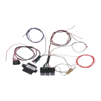
Mounting the resistor, controller, relays, and connecting the earth wire.
Fitting the switch into the console and connecting the red wire to ACC power.
Connecting the orange wire to the battery positive and grey wire to the negative terminal.
Explains activating High Speed Auto Mode, lock-up speed, and unlock speed.
Details activating Low Speed Lock Up, its speeds, and driving recommendations.
Information regarding a potential hot electrical smell during the first use of the resistor.
Discusses default settings, ideal speeds, and automatic unlocking behavior.
Visual and textual guide on using the dual switch for Automatic and Low Speed modes.
This document describes the installation and operation of a Torque Converter Lock Up Kit, specifically an Automatic Lock Up Controller, designed for Toyota Land Cruiser 100 Series models (HDJ100 and UZJ100) with 5-speed automatic transmissions manufactured between August 2002 and 2007. The kit enhances the vehicle's transmission control by allowing for both automatic low-speed and automatic high-speed torque converter lock-up.
The Torque Converter Lock Up Kit is an aftermarket electronic controller that modifies the behavior of the vehicle's automatic transmission, specifically the torque converter. In standard automatic transmissions, the torque converter allows for smooth power transfer but can introduce slippage, leading to heat generation and reduced fuel efficiency, especially at cruising speeds. The lock-up clutch within the torque converter is designed to eliminate this slippage, creating a direct mechanical link between the engine and transmission.
This kit provides an "Automatic Lock Up Controller" that allows the driver to manually or automatically engage the torque converter lock-up clutch at specific speeds, independent of the factory ECU's programming. This can result in improved fuel economy, reduced transmission fluid temperatures, and a more direct feel of power delivery, similar to a manual transmission. The controller intercepts and modifies the signals sent to the transmission's lock-up solenoid, enabling the lock-up clutch to engage earlier or under conditions not typically permitted by the stock ECU.
The system features an "ON OFF ON Switch" which likely refers to a three-way switch that controls the different operating modes of the lock-up controller. The core function is to provide "Automatic Low Speed Lock Up" and "Automatic High Speed Lock Up," indicating that the system can be configured to engage the lock-up clutch at different speed thresholds depending on the selected mode.
The kit offers distinct operating modes, selectable via a 3-way switch, each with specific engagement and disengagement parameters:
Automatic Mode (High Speed Auto Mode):
Low Speed Mode:
Factory Mode (In-active):
Pre-configured Settings: The controller comes pre-configured for automatic lock-up at approximately 80 km/h. This is considered an ideal speed for driving in 'D' mode with a locked converter. When slowing from speeds above 75 km/h with the converter locked, it automatically unlocks at approximately 75 km/h, eliminating the need for manual disengagement. These settings are optimized for subtle locking and unlocking actions and allow the vehicle to maintain a locked converter when transitioning from highway speeds to 80 km/h zones.
Tip-tronic Selection: For optimal performance at highway speeds with the converter locked, it is recommended to use the 'S' mode for tip-tronic selection in gear S6. This can encourage the transmission to select 6th gear more frequently, further enhancing efficiency.
The document provides some insights into the initial use and potential maintenance aspects:
Initial Use Odor: During the first use of the electronic torque converter lock-up kit, a hot electrical smell may be noticed inside the vehicle. This is considered normal and originates from the resistor as it heats up for the first time. This smell should dissipate within approximately 5 minutes once the operating temperature is achieved and should not re-occur after this initial period. This indicates that the resistor is a component that experiences significant heat during operation, and its proper functioning is crucial.
Wiring and Connections: The installation instructions emphasize the importance of secure connections. All wire joins must be soldered to ensure reliability and then insulated with heat shrink and/or electrical tape. This highlights the need for robust electrical connections to prevent intermittent issues or failures. Regular checks of these connections might be beneficial, especially if any unusual behavior is observed.
Cable Management: The instructions stress the importance of laying kit wiring back along the ECU connector harness and securing it with cable ties and electrical tape. This prevents strain on soldered connections and protects the cabling from damage due to chafing or movement. Proper cable management is a key maintenance practice to ensure the longevity and reliability of the installed kit.
Fuse Protection: The kit includes a fuse and fuse holder, which are critical for protecting the circuit from overcurrents. The instructions specify connecting the orange wire to the positive terminal of the vehicle's starter battery via the supplied fuse holder. It also explicitly states "Do NOT install the supplied fuse into the fuse holder at this time" during installation, implying it should be inserted only after all other connections are made and verified. This fuse acts as a safety device, and if the kit stops functioning, checking or replacing this fuse would be a primary troubleshooting step.
Power Source: The document explicitly warns against connecting the power wire to an auxiliary battery, stating it "may result in unpredictable behaviour of the unit." This indicates that the controller is designed to operate with the stable voltage provided by the main starting battery, and using an auxiliary power source might lead to performance issues or malfunctions. Adhering to the specified power source is a critical maintenance consideration for reliable operation.
Warranty: The kit comes with a 12-month warranty on all components. However, it explicitly states that "Richards Auto Electrical will not warrant any failures caused by modification to your vehicle." This is a standard clause that encourages proper installation and discourages unauthorized alterations to the vehicle's systems that could impact the kit's performance or cause damage.
Technical Support: Contact information for technical support is provided (08 85321411) for any queries or if there is a need to change the pre-configured values. This indicates that some parameters of the controller might be adjustable by the manufacturer or authorized personnel, suggesting a level of customizability beyond the user's direct control.
| Vehicle Model | Toyota Land Cruiser 100 Series |
|---|---|
| Production Years | 1998-2007 |
| ECU | Yes |
| ABS | Yes |
| SRS | Yes |
| Immobilizer | Yes |
| Bluetooth Connectivity | No |
| USB Port | No |
| Rear Seat Entertainment | Optional |
| Voice Control | No |
| Navigation System | Optional |
| Audio System | Varies by trim level. Included standard radio/cassette, radio/CD, and premium audio systems with multiple speakers and amplifiers. |
| Touchscreen Display | Optional |
| Steering Wheel Controls | Available |