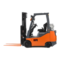
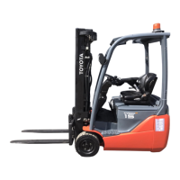
This document is a repair manual for Toyota 8FBCU and 8FBCHU series electric forklifts, specifically covering models 8FBCU 20, 25, 28, 30, 32, and 8FBCHU 25. It is Volume 1 of the manual, identified by Publication Number CU346.
The manual is structured into several sections, each dedicated to a specific system or component of the forklift. The sections included in this volume are:
- General (Section 0): This introductory section provides essential information on how to use the manual, general operational tips, and basic specifications.
- Battery (Section 1): Details related to the forklift's battery system.
- Control System (Section 2): Information on the electronic control systems.
- Multi-Function Display (Section 3): Covers the operation and troubleshooting of the multi-function display.
- Troubleshooting (Section 4): General troubleshooting guidelines.
- Motor (Section 5): Describes the forklift's motor.
- Drive Unit (Section 6): Focuses on the drive train components.
- Front Axle (Section 7): Details of the front axle assembly.
- Rear Axle (Section 8): Details of the rear axle assembly.
- Steering (Section 9): Information on the steering system.
- Brake (Section 10): Covers the braking system.
- Body (Section 11): Details related to the forklift's body structure.
- Material Handling System (Section 12): Describes the overall material handling mechanism.
- Mast (Section 13): Specific information about the mast assembly.
- Cylinder (Section 14): Covers the hydraulic cylinders.
- Oil Pump (Section 15): Details of the oil pump.
- Oil Control Valve (Section 16): Information on the oil control valve.
- SAS Functions (Section 17): Dedicated to the System of Active Stability (SAS) functions.
- Appendix (Section 18): Additional reference material.
Important Technical Specifications and Usage Features:
Vehicle Models and Load Capacities:
- Model Code 20: 4000 lbs (8FBCU20) - 36V/48V
- Model Code 25: 5000 lbs (8FBCU25, 8FBCHU25) - 36V/48V
- Model Code 28: 5500 lbs (8FBCU28) - 36V/48V
- Model Code 30: 6000 lbs (8FBCU30) - 36V/48V
- Model Code 32: 6500 lbs (8FBCU32) - 36V/48V (USA-CANADA-MEXICO only)
Frame Number Identification:
The frame number (punching position) is located on the vehicle. The punching format varies slightly by model and specification (e.g., EEC spec). For example, an 8FBCU20 uses the format 8FBCU25-60011, while an EEC spec 8FBCU25 uses *8FBCU25Ø60011.
How to Use This Manual:
The manual employs a specific explanation method for disassembly, inspection, and reassembly procedures. Step numbers in illustrations may be partially omitted. Tightening torque instructions are provided in N·m (kgf·cm) [ft·lbf] units, with part names described in the illustration frame if not directly indicated. Key points for operations are explained with illustrations, and specific inspection limits are provided (e.g., bush inside diameter limit: 19.12 mm (0.7528 in)).
Terminology and Abbreviations:
- Caution: Highlights important matters where negligence can cause hazards to human body.
- Note: Indicates important items to prevent breakage or breakdown, or special attention required during operation.
- Standard: Allowable range for inspection and adjustment.
- Limit: Maximum or minimum allowable value for inspection and adjustment.
Common abbreviations include ASSY (Assembly), ATT (Attachment), EHPS (Electronically controlled fully hydraulic power steering), FHPS (Fully hydraulic power steering), LH (Left hand), FR (Front), OPS (Operator Presence Sensing), OPT (Option), O/S (Oversize), PS (Power steering), RH (Right hand), RR (Rear), SAE (Society of Automotive Engineers (USA)), SAS (System of active stability), SOL (Solenoid), SST (Special service tool), STD (Standard), T= (Tightening torque), OOT (Number of teeth (○○)), U/S (Undersize), W/ (With), L/ (Less).
SI Units:
The manual adopts SI units (International System of Units) for consistency. A conversion rate table is provided for various units (Force, Torque, Pressure, Revolving speed, Spring constant, Volume, Power, Heat quantity, Specific fuel consumption) to facilitate conversion between conventional and SI units.
Operational Tips:
- Safe Operation: Always support jacked-up vehicles with wooden blocks or rigid stands. Use wire ropes with sufficient load capacity for hoisting. Disconnect the battery plug before servicing electrical parts.
- Tactful Operation: Prepare all necessary tools and measuring instruments (circuit tester, megger, oil pressure gauge, SSTs). Check cable color and wiring state before disconnecting. Arrange parts neatly during overhaul. Use clean tools for precision parts. Follow described procedures. Replace gaskets, packing, and O-rings with new ones. Use genuine Toyota parts. Observe specified tightening torques.
- Protection of Functional Parts: Thoroughly check connectors for failures or imperfect connections before reconnecting the battery plug, especially for controllers, as this can damage internal elements.
- Confirming Defect Status: Do not immediately disassemble or replace parts; first confirm if it's actually needed.
- Handling Waste Fluid: Always use appropriate containers for waste fluid. Dispose of oil, fuel, coolant, oil filters, batteries, and other harmful substances responsibly through authorized contractors.
- Handling Electronic Parts: Avoid impacts to electronic parts. Do not expose them to high temperature or humidity. Avoid touching connector pins to prevent deformation or damage from static electricity.
Battery Disconnection:
When unplugging the battery plug, always use the grip and avoid pulling the cable itself.
Jack-Up Point:
Strict instructions are provided for jacking up the vehicle:
- Unload any fork load and park on a flat floor.
- Use a jack with ample capacity at specified jack-up points.
- Never operate while the vehicle is held only by a jack; always support the frame with a wooden block after jacking up.
- Never place any body part under the jacked-up vehicle.
Illustrations clearly show the jack-up points and wooden block/stand setting points.
Hoisting the Vehicle:
- Use the mast hook on the front and a wire net on the rear wheel.
- Caution: Use wire ropes of sufficient strength. Never hoist by weight hook holes or the head guard.
Caution for Towing:
- Lift the rear wheels off the ground.
- Traveling speed must not exceed the forklift's maximum traveling speed.
- Set the key switch to OFF and the direction switch to neutral before towing. If an operator is on the forklift for PS operation, set the key switch to ON but keep the direction switch neutral.
- Remove the fork or secure it to prevent ground contact during towing.
Attentive Points on SAS (System of Active Stability):
- Refer to the separate manual "New Model Feature 8FBCU20 to 32 Pub. No.PU319" for SAS functions and operations.
- Read Section 17 "SAS Precautions for Repair" on Page 17-9 in this manual.
- After any repair or replacement related to SAS function, a machining procedure must be performed for SAS to regain proper function (See 17-18).
- Confirm the SAS caution label if modifications change original specifications (See Page 17-22).
- Exercise caution during operation, distinguishing between SAS-featured and non-SAS trucks due to different control features.
- SAS oil control valves are precision valves; dirty hydraulic oil will adversely affect them. Always clean parts during installation after disassembly or replacement of hydraulic parts. Periodic replacement of hydraulic oil is crucial.
- This vehicle uses high-precision electronic devices; modifications to electrical parts can cause faults. Use genuine Toyota parts for electrical replacements (auxiliary equipment, optional parts).
Circuit Tester Usage:
- Both analog and digital circuit testers are available and should be used selectively.
- Analog type: Good for observing movement during operation; measured values are for reference/rough judgment.
- Digital type: Provides fairly accurate readings; difficult to observe variation/movement.
- Difference in Measurement Results: Results may differ between analog and digital types. Always use according to the tester's operation manual. Cautions are provided for polarity differences.
- Analog Circuit Tester Example: Shows how continuity and resistance (in KΩ range) are measured in forward and reverse directions.
- Digital Circuit Tester Example: Shows how continuity and resistance (in MΩ range) are measured in forward and reverse directions.
- Difference in Result with Circuit Tester Power Supply Voltage: The power supply voltage of circuit testers (1.5V, 3.0V, or 6.0V) affects resistance measurements of semiconductors like diodes. This manual describes results using a 3.0V power supply.
- Difference in Measurement Result by Measurement Range (Analog Type): Changing the measurement range on an analog tester alters its internal circuit resistance, leading to varying results even for the same diode. Always use the range specified in the repair manual.
Standard Bolt & Nut Tightening Torque:
- For bolts and nuts without specified torques, use the standard tightening torque based on the bolt strength class.
- Identification by Bolt Shape:
- Hexagon head bolt: Identified by a number on the bolt head (e.g., 4 for 4T, 5 for 5T, etc.) or by protruding lines (Two lines for 5T, Three for 7T, Four for 8T). No mark indicates 4T.
- Welded bolt: No mark indicates 4T.
- Stud bolt: Grooved indicates 6T.
- Identification by Part No.: Part numbers (e.g., 91611-40625 for hexagon head bolt, 92132-40614 for stud bolt) also indicate length, diameter, and class.
- Tightening Torque Table: Provides specified torques (N·m, kgf·cm, ft·lbf) for various bolt diameters (6mm to 16mm) and pitches (1.0mm to 1.5mm) across different strength classes (4T, 5T, 6T, 7T, 8T). For example, a 6mm, 1.0 pitch, 4T bolt has a torque of 5.4 N·m (55 kgf·cm) [4 ft·lbf].