EasyManua.ls Logo

Toyota CQ-LS8180A User Manual

Toyota CQ-LS8180A
26 pages
To Next Page IconTo Next Page
Page #1 background imageLoading...
Page #1 background image
General
Power Supply DC 12V (11V - 16V),
Test Voltage 13.2V
Negative Ground
Current Consumption Less than 3.0A
Power Output 20W×4
AM Radio
Frequency Range
<CQ-LS8180A> 531 - 1,602 kHz
<CQ-LS8181A> 530 - 1,620 kHz
Usable Sensitivity 25dB/µV (S/N 20dB)
FM Stereo Radio
Frequency Range
<CQ-LS8180A> 87.5 - 108.0MHz
CQ-LS8180A
CQ-LS8181A
AM/FM MPX Electronic Tuning Radio
with Stereo Cassette Tape Player
PART No. (CQ-LS8180A) : 86120-33460
(CQ-LS8181A) : 86120-33440
ID CODE (CQ-LS8180A) : 57412
(CQ-LS8181A) : 57413
VEHICLE : COROLLA, CAMRY, ECHO, RAV4
DESTINATION
(CQ-LS8180A) : Australia, New Zealand,
Middle and Near East, China
(CQ-LS8181A) : Latin America
PRODUCED AFTER : Aug., 2001
<CQ-LS8181A> 87.9 - 108.0MHz
Usable Sensitivity 6dB/µV (S/N 30dB)
Cassette Player
Wow and Flutter 0.09% (WRMS)
Signal to Noise Ratio More than 42dB
Dimensions**(W×H×D) 178×70×165mm
Weight** 1.3kg
* Specifications and the design are subject to possible modification
without notice due to improvements.
** Dimensions and Weight shown are approximate.
Dolby noise reduction manufactured under license from Dolby
Laboratories Licensing Corporation.
“Dolby” and the double-D symbol
are trade marks of Dolby
Laboratories Licensing Corporation.
Specifications*
Question and Answer IconNeed help?

Do you have a question about the Toyota CQ-LS8180A and is the answer not in the manual?

Toyota CQ-LS8180A Specifications

General IconGeneral
TypeCar Receiver
ManufacturerToyota
BluetoothYes
USB PortYes
Max Power Output50W x 4
TunerAM/FM
DisplayLCD

Summary

1 FEATUERS

2 REAR VIEW AND CONNECTORS

3 FRONT VIEW AND FUNCTIONS

4 WIRING CONNECTION

5 BLOCK DIAGRAM

6 TERMINALS DESCRIPTION

7 PACKAGE AND IC BLOCK DIAGRAM

8 ALIGNMENT INSTRUCTIONS

Alignment Conditions

Specifies voltage, impedance, and control settings for calibration.

Dolby NR Alignment

Details steps for adjusting Dolby NR using test tapes and VTVM.

9 ALIGNMENT POINTS

10 REPLACEMENT PARTS LIST

11 EXPLODED VIEW (Unit)

12 TAPE PLAYER PARTS

13 EXPLODED VIEW (Tape Deck)

14 WIRING DIAGRAM

14.1 Main Block (Top View)

Top view of the main printed circuit board wiring.

14.2 Main Block (Bottom View)

Bottom view of the main printed circuit board wiring.

14.3 Display Block

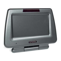
Wiring diagram for the display unit's printed circuit board.

14.4 Tape Block-1

Wiring diagram for the first part of the tape mechanism.

14.5 Tape Block-2

Wiring diagram for the second part of the tape mechanism.

15 SCHEMATIC DIAGRAM -1

15.1 Main Block

Detailed schematic of the main electronic control block.

15.2 Display Block

Detailed schematic of the display unit's circuitry.

16 SCHEMATIC DIAGRAM -2

16.1 Tape Block

Detailed schematic of the tape mechanism circuitry.

PARTS AVAILABILITY

Related product manuals