EasyManua.ls Logo

Toyota CQ-LS7230K User Manual

Toyota CQ-LS7230K
26 pages
To Next Page IconTo Next Page
Page #1 background imageLoading...
Page #1 background image
General
Power Supply DC 12V (11V - 16V),
Test Voltage 26.4V
Negative Ground
Current Consumption Less than 3.0A
Power Output 20W×4ch
AM Radio
Frequency Range 531 - 1,602kHz
Usable Sensitivity 30dB(µV) (S/N 20dB)
Signal to Noise Ratio 45dB or more
FM Stereo Radio
Frequency Range 87.5 - 108.0MHz
Usable Sensitivity 7dB/µV (S/N 30dB)
Signal to Noise Ratio 50dB or more
CQ-LS7230K
AM/FM MPX Electronic Tuning Radio
with Stereo Cassette Tape Player
PART No. : 86120-02360
VEHICLE : COROLLA
DESTINATION : INDIA
PRODUCED AFTER : Nov., 2002
Cassette Player
Reproduction System 4-Track, 2-Program Stereo
Tape Speed 4.76cm/sec.
Wow and Flutter Less than 0.09% (WRMS)
Signal to Noise Ratio 40dB or more
Dimensions** 178×50×165mm
Weight** 1.3kg
* Specifications and the design are subject to possible modification
without notice due to improvements.
** Dimensions and Weight shown are approximate.
Dolby noise reduction manufactured under license from Dolby
Laboratories Licensing Corporation.
“Dolby” and the double-D symbol
are trade marks of Dolby
Laboratories Licensing Corporation.
Specification*
Question and Answer IconNeed help?

Do you have a question about the Toyota CQ-LS7230K and is the answer not in the manual?

Toyota CQ-LS7230K Specifications

General IconGeneral
BrandToyota
ModelCQ-LS7230K
CategoryCar Receiver
LanguageEnglish

Summary

Audio Component Service Manual Overview

CQ-LS7230K Product Specifications

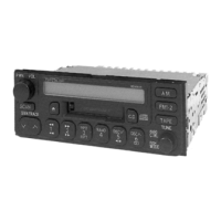
Detailed specifications for the CQ-LS7230K AM/FM MPX Electronic Tuning Radio with Stereo Cassette Tape Player.

System Features and Rear Connectivity

Rear Connector Pin Assignments

Pin assignments and function details for the CN702 12-pin and CN701 10P/6P rear connectors.

Front Panel Controls and Operation

Primary Control Functions

Functions of Push PWR, VOL, MODE, AM, FM, TAPE, CD, TUNE, TRACK, and SCAN controls.

Wiring Connection Diagram

System Block Diagram

Radio, Tape, and Amplifier Blocks

Functional blocks for Radio, Tape Player, Power Amplifier, and Muting circuits.

Control and Display System Blocks

Functional blocks for CPU, Display, and system control interfaces.

Terminal Descriptions

Main Block (IC601 C2BBGE000647) Terminals

Detailed description of each pin and its function for the Main Block IC601.

Display Block (IC601 YEAMLC75853) Terminals

Detailed description of each pin and its function for the Display Block IC601.

Alignment Procedures

Alignment Conditions and Setup

Specifies power supply, output impedance, and control settings for alignment.

Dolby NR Alignment Steps

Procedure for aligning Dolby NR Rch and Lch levels using test tapes.

Exploded View of the Unit

Tape Player Replacement Parts

Tape Deck Exploded View

Wiring Diagrams

Main Block Wiring Diagrams

Main Block PCB Layout

Tape Block Wiring Diagrams - Part 1

Tape Block Wiring Diagrams - Part 2

Fix-EQ. Block Wiring Diagrams

Schematic Diagrams - Part 1

Tape Block Circuit Schematic

Detailed circuit schematic for the Tape Player mechanism.

Schematic Diagrams - Part 2

Fix-EQ. Block Circuit Schematic

Detailed circuit schematic for the Fix-EQ. Block.

Schematic Diagram - Main/Display Block

Main and Display Block Circuit Schematic

Detailed circuit schematic for the Main and Display Blocks.

Related product manuals