EasyManua.ls Logo

Toyota 86120-02360 - User Manual

Toyota 86120-02360
26 pages
Print Icon
To Next Page IconTo Next Page
Loading...
General
Power Supply DC 12V (11V - 16V),
Test Voltage 26.4V
Negative Ground
Current Consumption Less than 3.0A
Power Output 20W×4ch
AM Radio
Frequency Range 531 - 1,602kHz
Usable Sensitivity 30dB(µV) (S/N 20dB)
Signal to Noise Ratio 45dB or more
FM Stereo Radio
Frequency Range 87.5 - 108.0MHz
Usable Sensitivity 7dB/µV (S/N 30dB)
Signal to Noise Ratio 50dB or more
CQ-LS7230K
AM/FM MPX Electronic Tuning Radio
with Stereo Cassette Tape Player
PART No. : 86120-02360
VEHICLE : COROLLA
DESTINATION : INDIA
PRODUCED AFTER : Nov., 2002
Cassette Player
Reproduction System 4-Track, 2-Program Stereo
Tape Speed 4.76cm/sec.
Wow and Flutter Less than 0.09% (WRMS)
Signal to Noise Ratio 40dB or more
Dimensions** 178×50×165mm
Weight** 1.3kg
* Specifications and the design are subject to possible modification
without notice due to improvements.
** Dimensions and Weight shown are approximate.
Dolby noise reduction manufactured under license from Dolby
Laboratories Licensing Corporation.
“Dolby” and the double-D symbol
are trade marks of Dolby
Laboratories Licensing Corporation.
Specification*
Question and Answer IconNeed help?

Do you have a question about the Toyota 86120-02360 and is the answer not in the manual?

Summary

Specifications

General and Performance Specs

Covers power, consumption, output, frequency ranges, sensitivity, and S/N ratios.

Physical Dimensions

Details the unit's dimensions and weight.

Features and Connectivity

Key Product Features

Lists core functionalities like PLL tuning, presets, Dolby NR, and CD control.

Rear Panel Connectors

Pinouts for CN702 (12-pin) and CN701 (10P/6P) connectors.

Front Panel Operations

Front View Controls and Functions

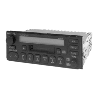
Explains the purpose of each button and control on the front panel.

Wiring Connections

System Interconnection Diagram

Shows how main PCB connects to other unit components like display and tape.

Block Diagram

Audio System Signal Flow

Illustrates signal paths for radio, tape, and audio amplification.

Terminal Descriptions

Main IC Terminal Details

Pinout and function for the main IC (IC601).

Display IC Terminal Details

Pinout and function for the display IC (IC601).

IC Block Diagrams

Main IC Block Diagram

Internal functional blocks of the main IC (PA101).

Alignment Procedures

Alignment Conditions and Dolby NR

Settings for alignment and steps for Dolby NR calibration.

Alignment Points

Adjustment Potentiometer Locations

Visual guide for locating VR201 (Rch) and VR301 (Lch) for Dolby NR adjustment.

Replacement Parts List

Component Part Numbers

Comprehensive list of replaceable components with part numbers.

Exploded View - Unit Assembly

Unit Disassembly Diagram

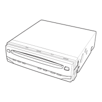
Illustrates the breakdown of the entire unit into sub-assemblies and parts.

Tape Player Parts

Tape Mechanism Component List

Detailed list of parts specific to the tape playback mechanism.

Exploded View - Tape Deck

Tape Deck Disassembly

Diagram showing the individual parts of the tape deck assembly.

Wiring Diagram - Display Block

Display PCB Layout

Top and bottom views of the display PCB showing component placement and traces.

Wiring Diagram - Main Block

Main PCB Top View

Top view of the main PCB illustrating component layout and wiring.

Main PCB Bottom View

Bottom view of the main PCB illustrating component layout and wiring.

Wiring Diagram - Tape Block 1

Tape PCB Top View Wiring

Wiring diagram for the tape PCB, top view.

Wiring Diagram - Tape Block 2

Tape PCB Bottom View Wiring

Wiring diagram for the tape PCB, bottom view.

Wiring Diagram - Fix-EQ Block

Fix-EQ PCB Layout

Top and bottom views of the Fix-EQ PCB showing component placement and traces.

Schematic Diagram - Tape Block

Tape Mechanism Circuit Schematic

Detailed circuit diagram for the tape player mechanism.

Schematic Diagram - Fix-EQ Block

Fix-EQ Circuit Schematic

Circuit diagram illustrating the fix equalization functionality.

Schematic Diagram - Main;Display Block

Main and Display Circuit Schematics

Detailed circuit diagrams for the main unit and display sections.

Parts Ordering Information

Replacement Parts Ordering Process

Instructions for ordering replacement parts from Toyota or Parts Depots.

Overview

This document describes the Toyota CQ-LS7230K, an AM/FM MPX Electronic Tuning Radio with a Stereo Cassette Tape Player. This device, with part number 86120-02360, is designed for the Corolla model in India and was produced after November 2002. It is manufactured for Toyota by Matsushita Electric Industrial Co., Ltd.

The CQ-LS7230K offers a range of audio and radio functionalities, making it a comprehensive in-car entertainment system.

Function Description:

The device integrates an AM/FM MPX electronic tuning radio with a stereo cassette tape player. It also features control capabilities for an external CD changer, enhancing its versatility as an audio source.

Radio Features:

  • PLL (Phase Locked Loop) synthesized tuning: This ensures precise and stable radio frequency reception.
  • 12-station preset: Users can store up to 12 favorite radio stations, with 6 for AM and 6 for FM, for quick access.
  • Scan tuning function: This allows the user to automatically scan through available radio frequencies to find stations.

Cassette Player Features:

  • 4-Track, 2-Program Stereo Reproduction System: This standard system provides stereo audio playback from cassette tapes.
  • Dolby B NR function: Integrated Dolby B Noise Reduction helps to reduce tape hiss and improve the overall sound quality of cassette playback.

General Audio Features:

  • Electronic volume control: This provides precise and convenient adjustment of audio levels.
  • Fix-Equalizing function: This feature likely offers pre-set equalization curves to optimize sound for different music genres or listening preferences.

Important Technical Specifications:

General:

  • Power Supply: Operates on DC 12V, with an allowable range of 11V to 16V. The test voltage is 26.4V.
  • Grounding: Negative Ground.
  • Current Consumption: Less than 3.0A.
  • Power Output: 20W x 4 channels, indicating a four-speaker output configuration.
  • Dimensions: 178 x 50 x 165 mm (Width x Height x Depth).
  • Weight: 1.3 kg.

AM Radio:

  • Frequency Range: 531 - 1,602 kHz.
  • Usable Sensitivity: 30 dB(µV) (S/N 20dB).
  • Signal to Noise Ratio: 45 dB or more.

FM Stereo Radio:

  • Frequency Range: 87.5 - 108.0 MHz.
  • Usable Sensitivity: 7 dB/µV (S/N 30dB).
  • Signal to Noise Ratio: 50 dB or more.

Cassette Player:

  • Reproduction System: 4-Track, 2-Program Stereo.
  • Tape Speed: 4.76 cm/sec.
  • Wow and Flutter: Less than 0.09% (WRMS), indicating good speed stability.
  • Signal to Noise Ratio: 40 dB or more.

Usage Features (Front Panel Controls):

The front panel provides intuitive controls for various functions:

  • PUSH PWR / VOL: Power ON/OFF and volume increase/decrease.
  • MODE: Selects audio adjustment modes.
  • AM / FM: Selects AM or FM radio mode.
  • TAPE: Selects tape mode.
  • CD: Selects CD changer mode.
  • TUNE Λ / TRACK Λ: Increases radio frequency or advances CD changer track.
  • TUNE V / TRACK V: Decreases radio frequency or reverses CD changer track.
  • SCAN: Initiates radio seek-up tuning or CD scan play.
  • 1~6 (Preset Buttons): Recalls preset radio frequencies.
  • DISC V / DISC Λ: Controls CD changer disc up/down.
  • SKIP: Tape blank skip function.
  • Rewind / Fast-Forward Buttons: Controls CD disc rewind/fast-forward and tape rewind/fast-forward.
  • RPT (Repeat): CD repeat play.
  • RAND (Random): CD random play.
  • PROG (Program): Tape program select.
  • Λ / V (Audio Level Adjustment): Adjusts audio levels.
  • Tape Eject Button: Ejects the cassette tape.
  • Cassette Slot: Where cassette tapes are inserted.
  • LCD Display: Shows current status and information.
  • Dolby B NR Indicator: Indicates when Dolby B Noise Reduction is active.

Maintenance Features:

The manual provides detailed information for maintenance and repair:

  • Rear View and Connectors: Illustrates the various connectors on the back of the unit, including those for speakers, power supply, and CD changer.
  • Wiring Connection: A block diagram showing the internal wiring between different PCB blocks (Display P.C.B., Main P.C.B., Tape P.C.B., Tape EQ P.C.B., Fix-EQ. P.C.B.).
  • Block Diagram: A comprehensive diagram outlining the functional blocks of the device, including AM/FM FE/MPX, PLL, CPU, Power Amp, Cassette Player components, and Display.
  • Terminals Description: Detailed tables listing the pin assignments, port descriptions, I/O type, and voltage for key ICs (IC601 Main Block, IC601 Display Block).
  • Package and IC Block Diagram: Provides internal block diagrams for major ICs like PA101 (Electronic Tuner), IC451 (PLL), IC201 (Audio Processor), IC631 (Motor Driver), IC651 (Driver Output), IC231 (Power Amplifier), and IC701 (Power Supply Control).
  • Alignment Instructions:
    • Alignment Conditions: Specifies the power supply voltage (DC13.2V), output impedance (4Ω), output power (0.5W), and control settings (Balance, Fader, Bass, Treble at center; Dolby NR OFF) for proper alignment.
    • Note: Emphasizes that the FM/AM package block is pre-aligned at the factory and should not be adjusted.
    • Dolby NR Alignment: Provides a step-by-step procedure for aligning Dolby NR for both Rch and Lch, including test tape (RFKZ0038), VTVM connection points (TP201, TP301), and adjustment points (VR201, VR301) to achieve 388mV ±1.0dB.
  • Alignment Points: A diagram showing the physical location of VR201, VR301, TP201, and TP301 on the Tape EQ P.C.B. [E-8790A].
  • Replacement Parts List: A comprehensive list of all replaceable components, including ICs, transistors, diodes, capacitors, resistors, connectors, coils, crystals, neon tubes, network resistors, switches, variable resistors, and mechanical parts. It also includes important safety notices regarding components with special characteristics (marked with a triangle) and retention time (RTL) for certain items.
  • Exploded Views: Detailed diagrams showing the exploded views of the main unit and the tape deck, aiding in disassembly and reassembly.
  • Wiring Diagrams: Separate wiring diagrams for the Display Block, Main Block (Top and Bottom Views), Tape Block -1, Tape Block -2, and Fix-EQ. Block, illustrating component placement and connections on the PCBs.
  • Schematic Diagrams: Detailed schematic diagrams for the Tape Block and Fix-EQ. Block, showing the electronic circuitry.
  • Main/Display Block Schematic Diagram: A comprehensive schematic diagram covering the main and display blocks.
  • Parts Availability and Ordering Information: Instructions on how to order replacement parts, emphasizing the importance of using the correct part number and unit number. It also lists various Panasonic Parts Depots globally for ordering.

The specifications and design are subject to possible modification without notice due to improvements. Dimensions and weight shown are approximate. The document also includes a note about Dolby noise reduction being manufactured under license from Dolby Laboratories Licensing Corporation, and that "Dolby" and the double-D symbol are trademarks of Dolby Laboratories Licensing Corporation.

Toyota 86120-02360 Specifications

General IconGeneral
BrandToyota
Model86120-02360
CategoryCar Receiver
LanguageEnglish

Related product manuals